Radio video transmission system and method

a radio video and transmission system technology, applied in the field of radio video system and transmission method, can solve the problems of inability to enable transmission, disadvantageous user interface, and inability of both radio video transmission system to transmit video data easily

Inactive Publication Date: 2006-10-12
SHARP KK
View PDF8 Cites 16 Cited by
  • Summary
  • Abstract
  • Description
  • Claims
  • Application Information

AI Technical Summary

Benefits of technology

[0017] These inventions enable appropriate video transmissions by switching a radio frequency band or a video data compression rate even if a radio environment is significantly degraded.

Problems solved by technology

Both radio video transmission systems may not transmit video data easily if their radio environments are degraded by interference by another piece of radio equipment or a change in the distance between a transmitter and a receiver resulting from operation during movement.
However, these systems cannot enable the transmission if the radio environment is degraded to the degree that the receiver cannot transmit the instruction on the switching of the radio frequency band or the video data compression rate, to the transmitter.
Accordingly, this user interface is disadvantageous.

Method used


Image

  • Radio video transmission system and method
  • Radio video transmission system and method
  • Radio video transmission system and method

Examples


first embodiment

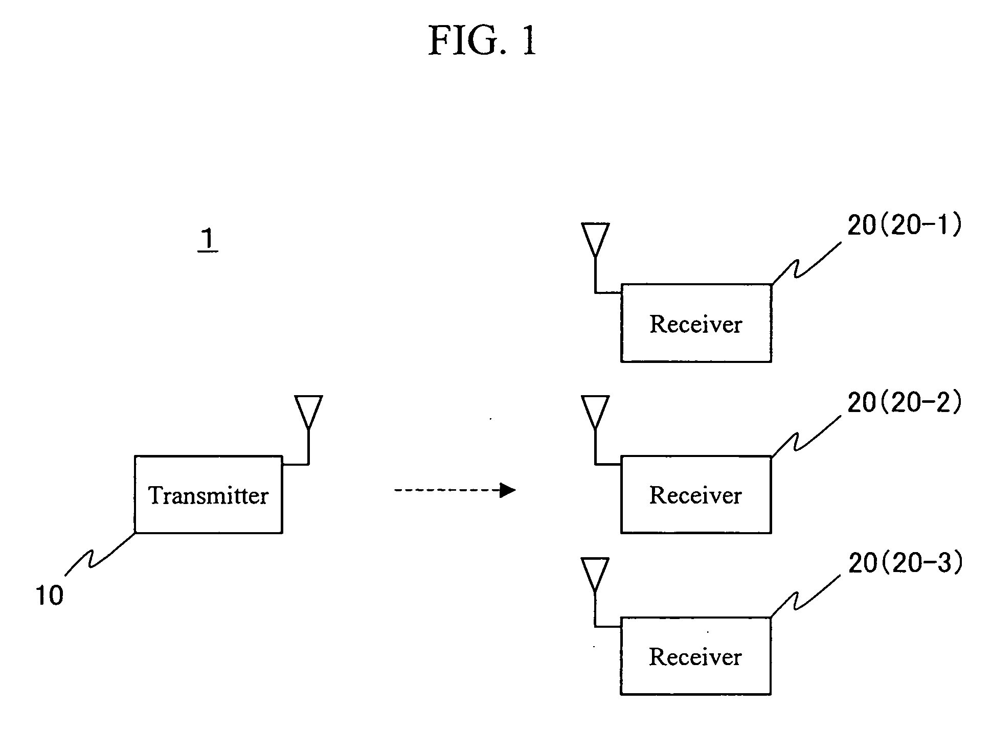
[0051]FIG. 1 is a diagram showing the configuration of a radio video transmission system according to the present embodiment.

[0052] For simplification, a radio video transmission system 1 according to the present embodiment comprises one transmitter 10 and three receivers 20-1, 20-2, and 20-3. The transmitter 10 and the receivers 20-1 to 20-3 are connected together using the radio transmission system based on the spectrum spread communication.

[0053] In the radio video transmission system 1 according to the present embodiment, the transmitter 10 transmits one or more video sources, which are received by the receivers 20-1 to

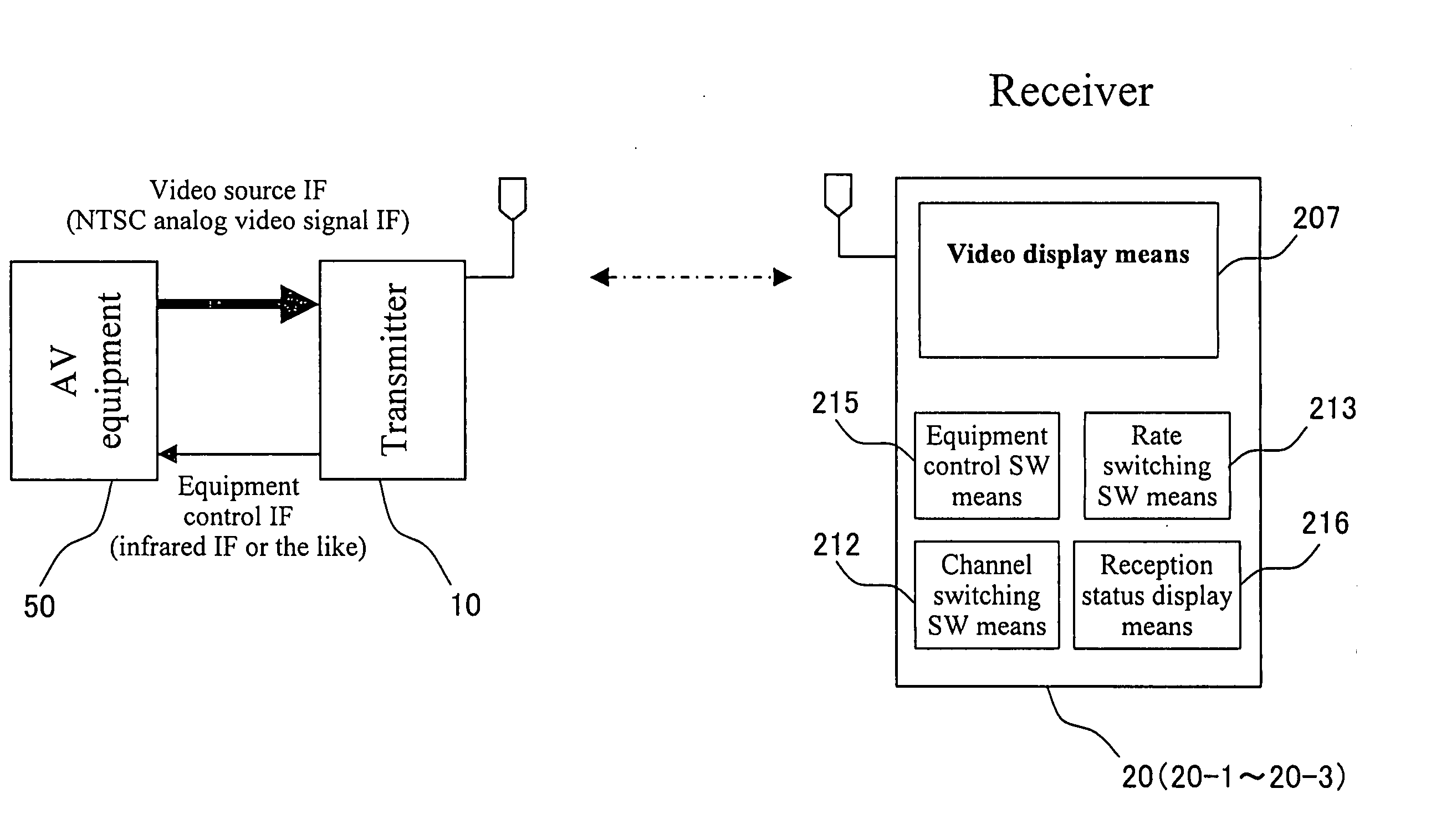
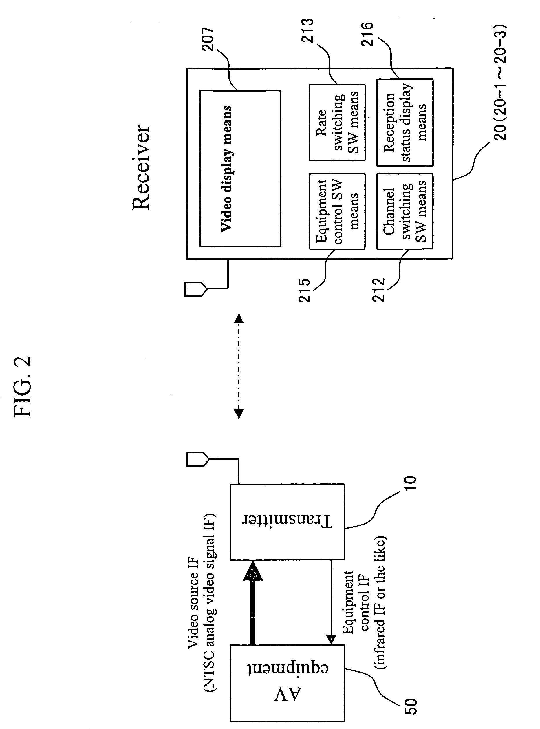
[0054]FIG. 2 is a diagram schematically showing equipment applied to the radio video transmission system according to the present embodiment.

[0055] The transmitter 10 is connected to AV equipment 50 such as a VTR (Video Tape Recorder), a TV tuner, or a DVD (Digital Versatile Disk) player. As an interface for video sources, the AV equipment 50 supplies NTSC (Na...

second embodiment

[0253] Now, with reference to FIG. 18, description will be given of a second embodiment of a system and method for radio video transmission according to the present invention.

[0254]FIG. 18 is a diagram showing the configuration of a transmitter according to the second embodiment.

[0255] The second embodiment corresponds to the first embodiment characterized in that a timer 112 is provided in the channel switching processing means 109 of the transmitter 10 and in that each of the processing means 105 to 108, 110, and 111 enclosed by a dotted line in FIG. 18 comprises a power saving mode function for stopping a supplied driving clock or a power supply.

[0256] When the periodic status message from the receiver 20 is discontinued and the transmitter 10 attempts to find an available channel for connection, the timer 112 counts the time spent in switching the channel.

[0257] Description will be given of the system and method for radio video transmission according to the present embodimen...

third embodiment

[0264] Now, with reference to FIG. 19, description will be given of a third embodiment of a system and method for radio video transmission according to the present embodiment.

[0265]FIG. 19 is a diagram showing the configuration of a receiver according to the third embodiment.

[0266] In the third embodiment, the reception status analyzing means 208 of the receiver 20 according to the first embodiment, shown in FIG. 7, comprises a process of analyzing the reception status (ratio of the error count to the reception count) of the receiver 20 and instructing the rate switching processing means 210 to switch the rate.

[0267] According to the present embodiment, the reception status analyzing means 208 additionally has an automatic transmission rate adjusting function. With this function, for example, while video is being transmitted between the transmitter 10 and the receiver 20 at a transmission rate of 6 Mbps, when the reception status (ratio of the error count to the reception count) ...


PUM


Abstract

The present invention provides a system and method for radio video transmission which switches a radio frequency band or a compression rate for video data to enable appropriate video transmission even if a radio environment is degraded. A pair of a transmitter 10 and a receiver 20 transmits video data in the radio environment. The receiver 20 periodically transmits a status message to the transmitter 10. If the transmitter 10 fails to receive reception of the periodically transmitted status message, the failure is used as a trigger to cause the transmitter 10 to switch the channel (radio frequency band) or the video data compression rate. It is therefore possible to switch the radio frequency band or video data compression rate for the transmitter 10 and receiver 20 even if the radio environment is degraded.

Description

TECHNICAL FIELD [0001] The present invention relates to a system and method for radio video transmission which transmits video data by radio. BACKGROUND ART [0002] Conventional radio video transmission systems transmitting video data by radio include those which transmit video data from AV (Audio & Visual) equipment using a very weak radio wave and those which are utilized for Wireless LAN (Local Area Network) and which use a spectrum spread communication. [0003] A television signal transmission apparatus described in JP Utility Model Publication (Kokai) No. 3-482 U (1991) is a specific example of a system transmitting video data using a very weak radio wave according to the above conventional technique. A radio video signal transmission and reception apparatus described in JP Patent Publication (Kokai) No. 10-173571 A (1998) is a specific example of a system transmitting video data using a spectrum spread communication. [0004] Both radio video transmission systems may not transmit ...

Claims


Application Information

Patent Timeline
Patent Type & Authority Applications(United States)
IPC IPC(8): H04N7/173H04N9/47H04N17/02H04N7/18H04N17/00H04L1/00H04L1/22H04N21/2381
CPCH04L1/0023H04L1/0014
Inventor YAMAUCHI, MASAHIRO
Owner SHARP KK
Why Eureka
Try Eureka