Safety tester having a high-voltage switching relay protected by an in-line electronic circuit breaker

Inactive Publication Date: 2006-10-12
ASSOCD RES
View PDF12 Cites 9 Cited by
  • Summary
  • Abstract
  • Description
  • Claims
  • Application Information

AI Technical Summary

Benefits of technology

[0012] It is a first objective of the invention to provide a multiple function electrical te

Problems solved by technology

Short circuits that occur in the DUT during line voltage tests, or that occur during changing of a test set-up, can draw sufficient current to damage the high voltage switching relay.
The line voltage source controlling relay and the switching relay are both relatively expensive components and contribute significantly to the ove

Method used


Image

  • Safety tester having a high-voltage switching relay protected by an in-line electronic circuit breaker
  • Safety tester having a high-voltage switching relay protected by an in-line electronic circuit breaker
  • Safety tester having a high-voltage switching relay protected by an in-line electronic circuit breaker

Examples


Embodiment Construction

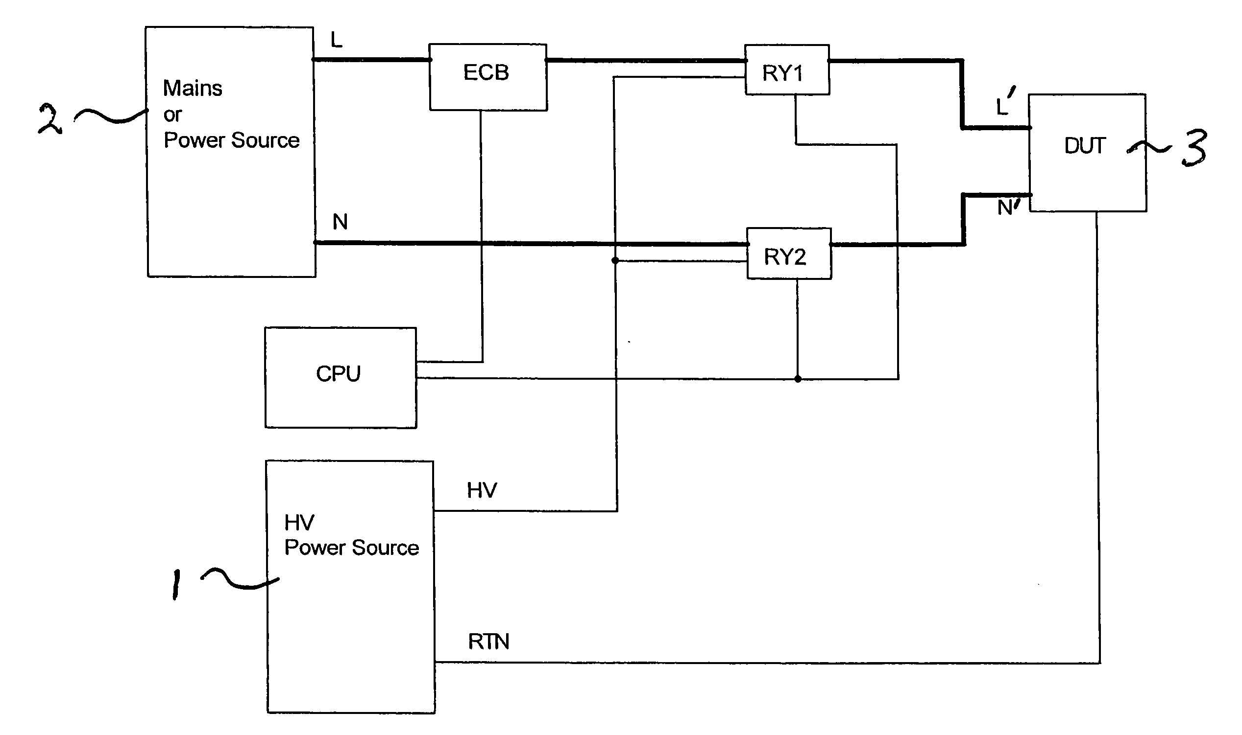
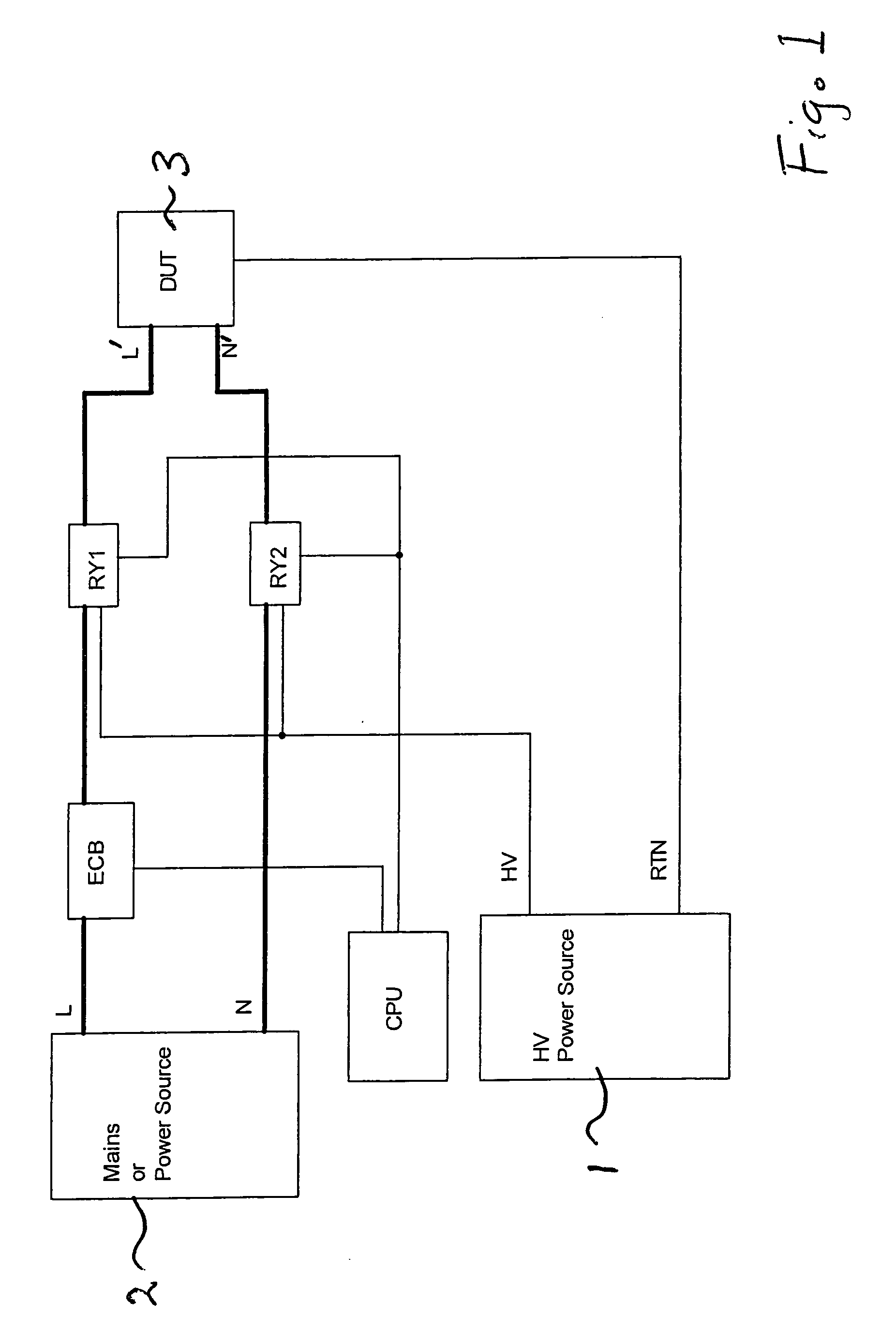
[0024] As illustrated in FIG. 1, the preferred safety compliance test instrument includes a high voltage power source 1 having a high voltage output HV and a return RTN, and a mains or line voltage power source 2 having a live output L and a neutral N. High voltage output HV of high voltage source 1 and line voltage output L of line voltage source 2 are selectively connected to a DUT 3 via a corresponding port L′ of the test instrument and high voltage relay RY1. The neutral connection between the line voltage source neutral N and the neutral output N′ of the test instrument is switched by a second output switching relay RY2, which may also be connected to high voltage source output HV in order to provide a second output port for high voltage tests. The DUT return is typically directly connected to return RTN of the high voltage source. A central processing unit CPU controls switching of the respective relays RY1 and RY2 according to the type of test to be run. Appropriate operator ...


PUM


Abstract

A multiple function safety compliance test instrument includes a high voltage output switching relay protected by a solid state in-line circuit breaker.

Description

BACKGROUND OF THE INVENTION [0001] 1. Field of the Invention [0002] This invention generally relates to the field of electrical safety compliance testing, and more particularly to a multiple function safety compliance test instrument that includes: [0003] a high voltage output switching relay for selectively supplying power from either a line voltage source or a high voltage source to a device under test (DUT); and [0004] a circuit breaker for protecting the high voltage output switching relay from high currents. [0005] The invention replaces the conventional circuit breaking relay or fuse with a protective circuit that includes transistors connected in series between the line voltage source and the switching relay, the transistors having a relatively small ON resistance to enable the transistors to carry currents during the entire test time and not just at start-up. The short turn-off time of the series-connected transistors reduces the current-carrying requirements of the high vol...

Claims


Application Information

Patent Timeline
IPC IPC(8): H02H3/00
CPCG01R31/3278G01R31/3275
Inventor BALD, ROGER A.CHEN, PIN-YI
Owner ASSOCD RES
Why Eureka
Try Eureka