
Metal/fullerene anode structure and application of same

a technology of anode structure and metal, applied in the field of metal/fullerene anode structure, can solve the problems of power loss, significant voltage drop across the ito electrode, and limited use of ito, and achieve the effect of efficient hole injection

Inactive Publication Date: 2006-10-12
LU ZHENG HONG +2
View PDF19 Cites 37 Cited by
  • Summary
  • Abstract
  • Description
  • Claims
  • Application Information

AI Technical Summary

Benefits of technology

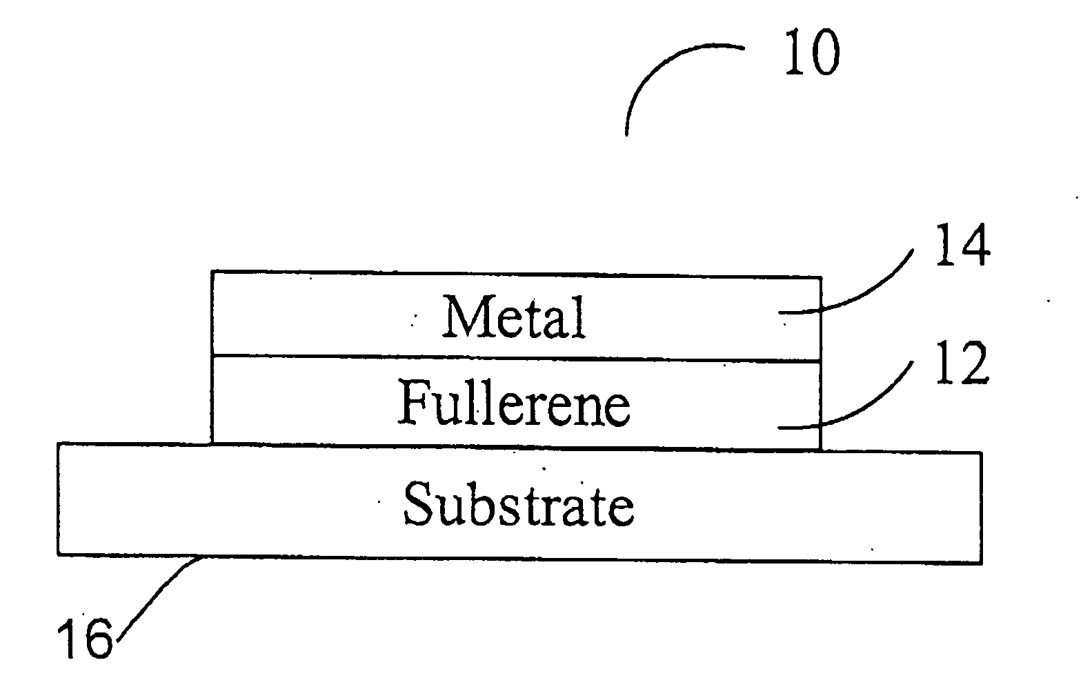
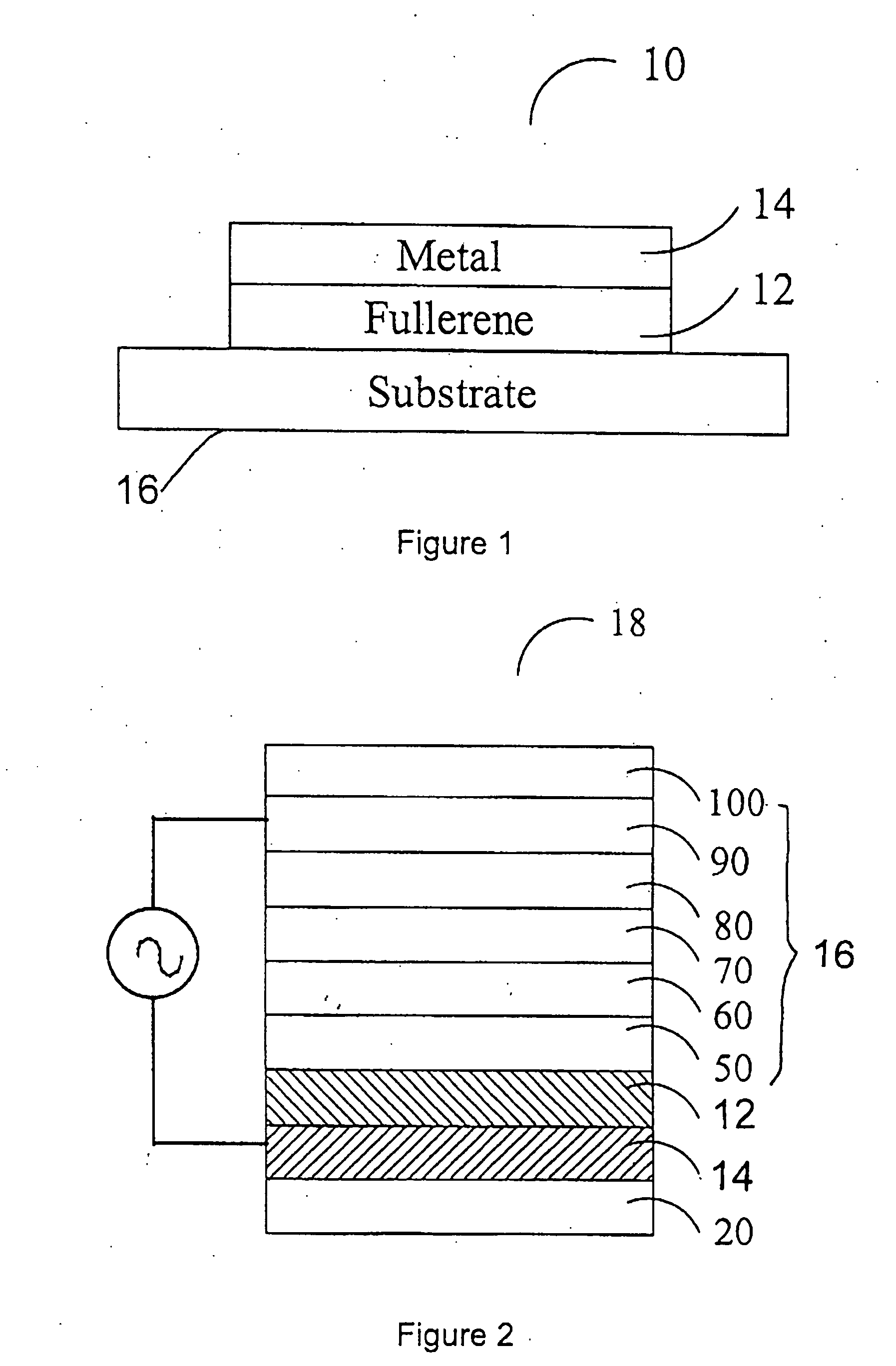
The present invention provides a metal / fullerene layered structure for efficient hole injection into a molecular system or thin-film device. This structure can be used as the anode in an organic-based electroluminescence device, replacing the current problematic ITO anode or simple metal anode. The layered electrically conductive material / fullerene anode structure exhibits hole injection behavior across the first and second layers, and the light-emitting device comprising this structure has improved performance and stability. The invention also provides a semi-transparent electrode that allows the light emitted from the device to exit.

Problems solved by technology

The use of ITO is also limited because of its deposition and post-deposition annealing require temperatures in excess of 200° C., which may, for example, exclude the use of flexible plastic substrates in a roll-to-roll type fabrication process.
This leads to significant voltage drops across the ITO electrode and hence power loss and non-uniformity in light output.

Method used


Image

  • Metal/fullerene anode structure and application of same
  • Metal/fullerene anode structure and application of same
  • Metal/fullerene anode structure and application of same

Examples


Embodiment Construction

Definitions

[0041] As used herein, the phraseelectron transport layer (ETL)” means a thin-film material having a primary function of conducting or transporting electrons across the layer from one region to another region.

[0042] As used herein, the phrase “hole transport layer (HTL)” means a thin-film material having a primary function to conduct holes across the layer from one region to another region.

[0043] As used herein, the phrase “light emissive layer” or “light-emission layer” means a thin-film material having the primary function of emitting light.

[0044] As used herein, the phrase “electroluminescence layer (EL)” means a thin-film material having a primary function of emitting light under electrical stimulation.

[0045] As used herein, the phrase “hole injection layer (HIL)” means a thin-film materials having a primary function of enhance hole injection from anode to the HTL.

[0046] As used herein, the phrase “metal / fullerene anode” means a layered structure consisting o...


PUM

PropertyMeasurementUnit
thicknessaaaaaaaaaa
thicknessaaaaaaaaaa
thicknessaaaaaaaaaa

Abstract

The present invention provides a layered metal / fullerene anode structure for efficient hole injection. The layered anode structure includes one or more layers of electrical conductors and a second layer containing fullerenes. The thickness of the second layer is selected so that the layered structure facilitate hole transfer from the layer to second layer under electrical bias. The present invention also provides a light-emitting device which includes a layered metal / fullerene anode. The device includes an hole transport layer, and a second electrically conductive layer defining a cathode electrode layer. The device includes a layer of light-emissive material between the hole transport layer and the cathode electrode. The device may also include a hole injection layer interposed between the layered metal / fullerene anode and the hole transport layer. The device may also include a dielectric layer attached to the metal layer of the layered metal / fullerene anode.

Description

CROSS REFERENCE TO RELATED APPLICATIONS [0001] This patent application claims the priority benefit from U.S. Provisional Patent Application Ser. No. 60 / 670,244 filed on Apr. 12, 2005 entitled METAUFULLERENE ANODE STRUCTURE AND APPLICATION OF SAME, which is incorporated herein by reference in its entirety.FIELD OF THE INVENTION [0002] The present invention relates to metal / fullerene anode structure for efficient hole injection and more particularly the present invention relates to use of metal / fullerene anode for highly efficient organic-based light-emitting devices (OLEDs), replacing the problematic metal oxides anode. BACKGROUND OF THE INVENTION [0003] A typical organic light-emitting device (OLED) includes an anode, an active light-emitting zone comprising one or more electroluminescent organic material(s), and a cathode. One of the electrodes needs to be optically transmissive while the other electrode can be optically reflective. The function of the anode is to inject positively...

Claims


Application Information

Patent Timeline
Patent Type & Authority Applications(United States)
IPC IPC(8): B32B15/04B32B5/16H01L51/50H05B33/26
CPCB82Y10/00H01L51/0046H01L51/0048Y10T428/265H05B33/28Y02E10/549Y10T428/25H01L51/5206Y10T428/31678H10K85/211H10K85/221H10K50/816H10K2102/321
Inventor LU, ZHENG-HONGHAN, SIJINYUAN, YANYAN
Owner LU ZHENG HONG
Learn More