Point-to-multipoint communications system and method

a communication system and multi-point technology, applied in the field of communication systems, can solve the problems of performance limitations and significant gain loss, and achieve the effect of easy control of adding

Active Publication Date: 2006-10-12
THE BOEING CO
View PDF51 Cites 51 Cited by
  • Summary
  • Abstract
  • Description
  • Claims
  • Application Information

AI Technical Summary

Benefits of technology

[0005] Thus, the system and method enables simultaneous one way communication channels, or full duplex communication channels, to be formed with a plurality of independent, remotely located communications terminals, via a single beam. The independent steerability of the lobes of the single beam allow the communication channels to be maintained regardless if the remote terminals are moving in divergent directions. The system can be easily controlled to add or delete coverage lobes to accommodate changing numbers of remote terminals. Since the coverage lobes can be narrowly focused on each of the remote terminals, gain is not wasted to cover the full azimuthal region in between the two terminals, but is more efficiently used by the two narrowly focused lobes of the single beam.
[0006] An additional advantage of the independently steerable lobes of the single beam is that the signal gain associated with each lobe can be independently controlled. Thus, if one lobe has established a communications link with a remote terminal that is located in an area experiencing poor weather, the gain of the lobe can be controlled to compensate for this. Alternatively, the gain of each lobe can be controlled by the beam forming network to implement different data rates of communication with different remote terminals. Still further, the gain of each lobe can be tailored to best (and most efficiently) communicate with remote terminals located at different distances from the base station.

Problems solved by technology

This obviously has performance limitations.
For example, a base station that generates a single lobe beam for communicating with a pair of remote terminals within an azimuth angular section of ±15 degrees would be required to “spread” the coverage pattern of a lobe over an azimuth sector of 30 degrees, which may result in a significant gain loss.

Method used


Image

  • Point-to-multipoint communications system and method
  • Point-to-multipoint communications system and method
  • Point-to-multipoint communications system and method

Examples


Embodiment Construction

[0035] The following description of the preferred embodiment(s) is merely exemplary in nature and is in no way intended to limit the invention, its application, or uses.

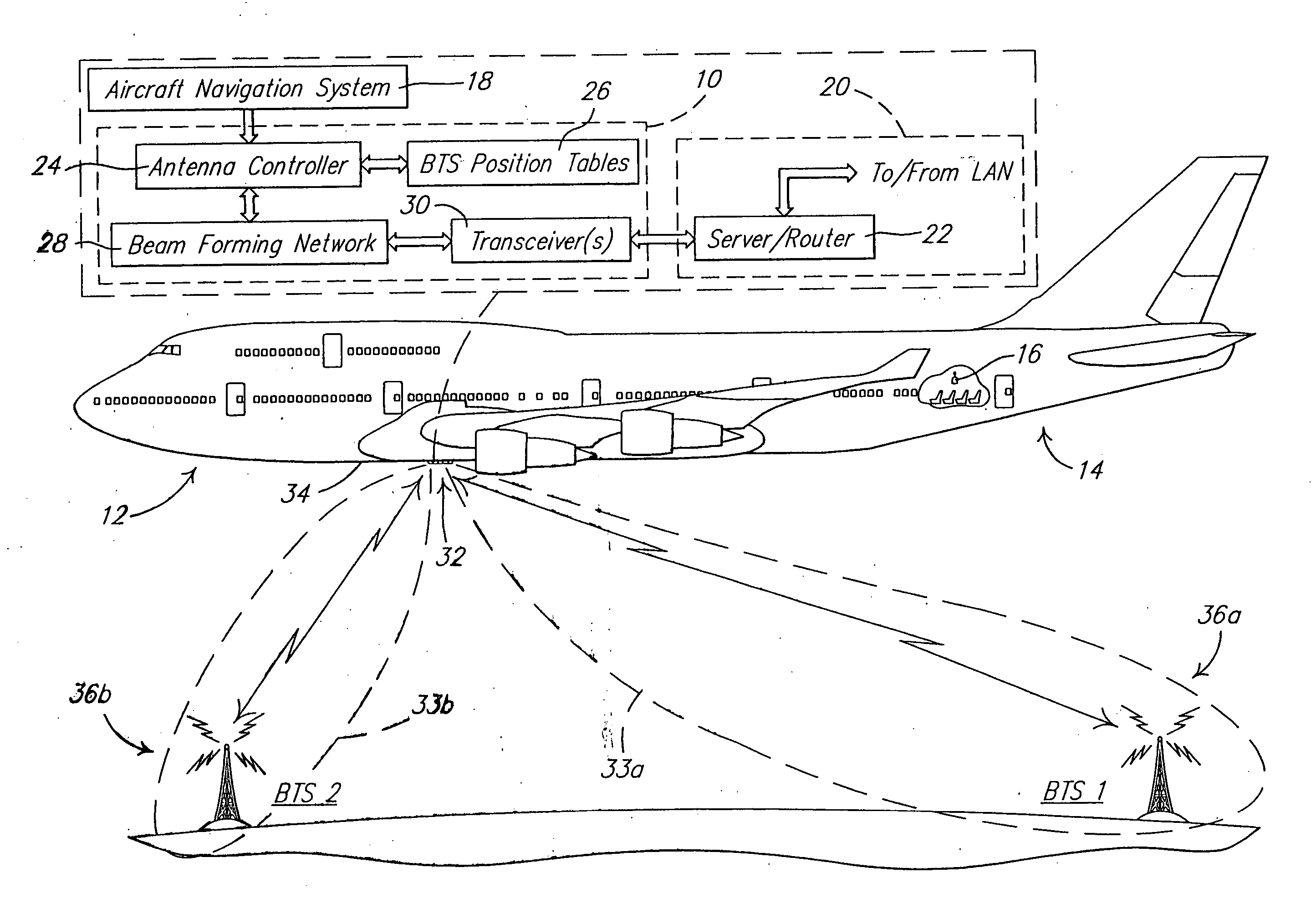
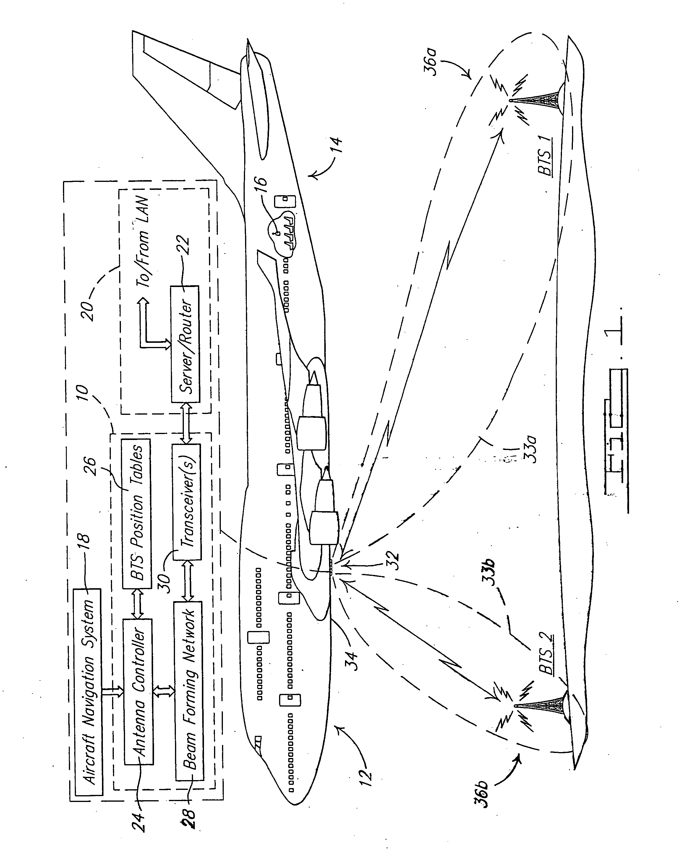
[0036] Referring to FIG. 1, there is shown an aircraft radio terminal (ART) 10 in accordance with a preferred embodiment of the present invention. The ART 10 is implemented, in this example, on a commercial aircraft 12 having a fuselage 14. One or more occupants on the aircraft 12 have in his / her possession a cellular telephone 16, which alternatively could form a wireless personal digital assistant (PDA). The aircraft 12 includes an aircraft navigation subsystem 18 and an on-board network 20 that incorporates a server / outer 22 in communication with a local area network (LAN) implemented on the aircraft 12. Although not shown, it will be appreciated that the LAN implemented on the aircraft 12, in one preferred form, makes use of a plurality of wireless access points spaced throughout the interior cabin area of the a...


PUM


Abstract

A point-to-multipoint communications system. The system uses an antenna to generate a single beam having independently steerable, narrow lobes. The phase array and amplitude array distributions used to form the lobes are controlled so that the lobes track and provide full duplex communication links with two or more RF terminals in two or more remote locations. In certain embodiments the dual lobe beam is generated from a fixed, ground-based location, and in other embodiments the single beam is generated from an airborne mobile platform, a mobile land vehicle, or a marine vessel. The various embodiments all enable one, two or more full duplex communication links to be established and maintained with a single beam.

Description

CROSS-REFERENCE TO RELATED APPLICATIONS [0001] This present application is a continuation-in-part of U.S. Ser. No. 11 / 184,712, filed Jul. 19, 2005, which claims priority from U.S. Provisional Patent Application No. 60 / 669,950 filed on Apr. 8, 2005, both of which are hereby incorporated by reference into the present application. The present invention is also generally related to the subject matter of U.S. patent application Ser. No. 11 / 184,764, filed Jul. 19, 2005, and assigned to The Boeing Company, the disclosure of which is also incorporated herein by reference into the present application.FIELD OF THE INVENTION [0002] The present invention relates to communication systems, and more particularly to a point-to-multipoint communications system having a base station that is able to communicate simultaneously with a pair of remotely located terminals, via a plurality of independently steerable lobes of a single antenna beam generated from the base station. BACKGROUND OF THE INVENTION ...

Claims


Application Information

Patent Timeline
Patent Type & Authority Applications(United States)
IPC IPC(8): H04M1/00H04W84/06
CPCH04B7/18506H04W84/06H04W36/18H04W36/08H01Q3/2658H01Q19/192H01Q1/283H01Q1/3208
Inventor MONK, ANTHONY D.
Owner THE BOEING CO
Why Eureka
Try Eureka