Diagnostic imaging system and image processing system

a technology of image processing system and diagnostic imaging system, which is applied in image enhancement, instruments, applications, etc., can solve the problems of inefficiency of interpretation and diagnosis, inability to manually check regions, and inability to easily display regions, so as to reduce the time for searching a targeted active region by users, and efficiently make a diagnosis and a diagnostic reading

Inactive Publication Date: 2006-10-12
TOSHIBA MEDICAL SYST CORP
View PDF8 Cites 96 Cited by
  • Summary
  • Abstract
  • Description
  • Claims
  • Application Information

AI Technical Summary

Benefits of technology

[0012] The present invention has taken into consideration the above-described problems, and it is an object of the present invention to provide a diagnostic imaging system and an image processing system such that it efficiently make a diagnosis and a diagnostic reading by a user, by reducing a time for searching a targeted active region by the user.
[0019] Therefore, according to the present invention to provide the diagnostic imaging system and the image processing system, it is possible to efficiently make a diagnosis and a diagnostic reading by a user, because a time for searching a targeted active region by the user can be reduced.

Problems solved by technology

However, with the display operation via the virtual endoscopy using the three-dimensional image data having only the morphological image, although the shape, size, and position, of the active region can manually be checked, the state of the active region cannot manually be checked.
Thus, the observation of the targeted active region consumes time and labor, an image of the active region is not easily displayed, and the interpretation and diagnosis are not efficient.
Furthermore, even if obtaining the targeted image, the display format of the image is insufficient, e.g., the viewpoint with the active region for observation as center is not automatically determined.
Therefore, diagnostic information is not presented sufficiently to the doctor, etc. and this does not enable the efficient diagnosis.
In this case, the search of the active region consumes labor and time and the efficient interpretation and diagnosis are not possible.
Further, there is a danger of the miss of the active region.

Method used


Image

  • Diagnostic imaging system and image processing system
  • Diagnostic imaging system and image processing system
  • Diagnostic imaging system and image processing system

Examples


first embodiment

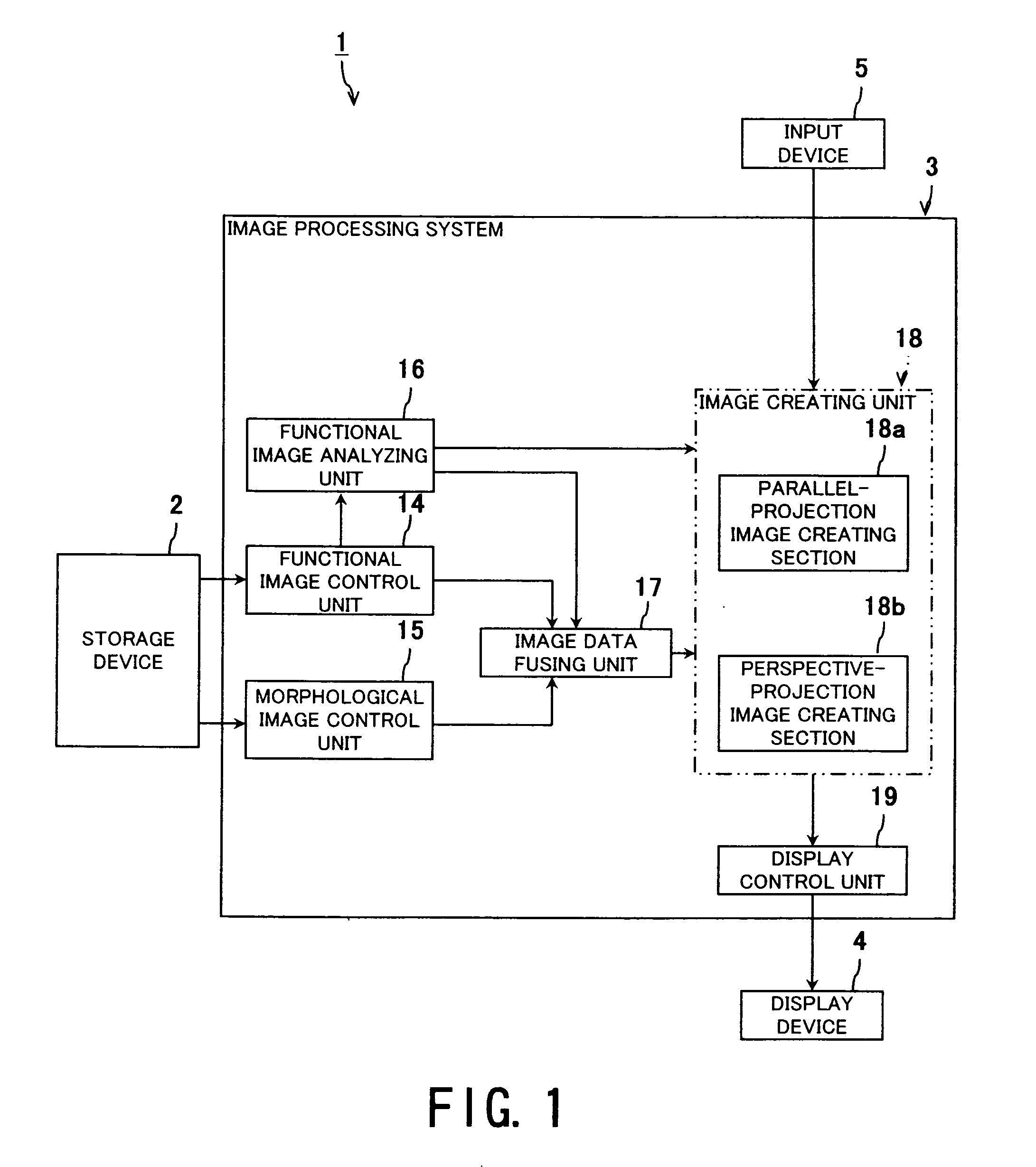
[0046]FIG. 1 is a block diagram showing a structure of a diagnostic imaging system and an image processing system according to a first embodiment of the present invention.

[0047] Referring to FIG. 1, a diagnostic imaging system 1 is shown, and the diagnostic imaging system 1 comprises a storage device 2, an image processing system 3, a display device 4, and an input device 5. Note that the diagnostic imaging system 1 includes therein, the storage device 2, the image processing system 3, the display device 4, and the input device 5 as shown in FIG. 1, however, the present invention is not limited to this structure, and the diagnostic imaging system 1 may externally have a part or all of the storage device 2, the image processing system 3, the display device 4, and the input device 5.

[0048] The storage device 2 comprises a hard disk, a memory and so on, and mainly stores functional image data and morphological image data. Specifically, the storage device 2 stores the functional image...

second embodiment

[0110]FIG. 13 is a block diagram showing a structure of a diagnostic imaging system and an image processing system according to a second embodiment of the present invention.

[0111] Referring to FIG. 13, a diagnostic imaging system 1A is shown and the diagnostic imaging system 1A comprises the storage device 2, an image processing system 3A, the display device 4 and the input device 5. Note that the diagnostic imaging system 1A includes therein the storage device 2, the image processing system 3A, the display device 4, and the input device 5, as shown in FIG. 13. However, the present invention is not limited to this structure. For example, diagnostic imaging system 1A may externally have a part or all of the storage device 2, the image processing system 3A, the display device 4, and the input device 5.

[0112] The image processing system 3A comprises the units 14 to 19 arranged to the image processing system 3 described with reference to FIG. 1 and further comprises a display-priority...

third embodiment

[0150]FIG. 18 is a block diagram showing a structure of a diagnostic imaging system and an image processing system according to a third embodiment of the present invention.

[0151] Referring to FIG. 18, a diagnostic imaging system 1B is shown and the diagnostic imaging system 1B comprises the storage device 2, a image processing system 3B, the display device 4, and the input device 5. Although the diagnostic imaging system 1B includes the storage device 2, the image processing system 3B, the display device 4, and the input device 5, as shown in FIG. 18, the present invention is not limited to this structure. The diagnostic imaging system 1B may externally have a part or all of the storage device 2, the image processing system 3B, the display device 4, and the input device 5.

[0152] The image processing system 3B comprises a morphological image analyzing unit 42 in addition to the units arranged to the image processing system 3A described with reference to FIG. 13. According to the th...


PUM


Abstract

A functional image analyzing unit in an image processing system extracts an active region from the functional information data, serving as volume data, and a display-priority determining unit determines the display-priority on the basis of a volume of the active region or a voxel value of the active region. An image data fusing unit fuses functional image data and morphological image data to create fused-image data, and an image creating unit receives the fused-image data and sequentially creates three-dimensional image data in accordance with the display-priority. A display control unit allows a plurality of pieces of the three-dimensional image data to sequentially be displayed on a display. Herewith, it is possible to efficiently make a diagnosis and a diagnostic reading by a user, because a time for searching a targeted active region by the user can be reduced.

Description

BACKGROUND OF THE INVENTION [0001] 1. Field of the Invention [0002] The present invention relates to a technology, with which, an image indicating a region for observation is created and displayed on the basis of a morphological image captured by an X-ray computerized tomography (X-ray CT) apparatus, a magnetic resonance imaging (MRI) apparatus, or an ultrasonic diagnostic apparatus and a functional image captured by a nuclear medicine diagnostic apparatus or a functional-magnetic resonance imaging (f-MRI) apparatus. In particular, the present invention relates to a diagnostic imaging system and an image processing system that roughly specify the position of the lesion with the functional image and finely observes the position and the shape of the lesion on the morphological image. [0003] 2. Description of the Related Art [0004] In general, the clinical diagnosis includes a morphological diagnosis and a functional diagnosis. Importantly in view of the clinical diagnosis, it is deter...

Claims


Application Information

Patent Timeline
Patent Type & Authority Applications(United States)
IPC IPC(8): A61B5/05G06K9/00A61B5/00A61B8/08G06T1/00G06T3/00G06T15/08
CPCG06T5/50G06T7/0012G06T7/0081G06T2200/04G06T2207/30101G06T2207/10072G06T2207/20221G06T2207/30096G06T2200/24G06T7/11
Inventor WAKAI, SATOSHI
Owner TOSHIBA MEDICAL SYST CORP
Why Eureka
Try Eureka