Device control method and device control system

a device control and control method technology, applied in automatic control, electric controllers, instruments, etc., can solve the problems of increasing the number of combinations of inputs and outputs, increasing energy consumption, and difficulty in learning

Inactive Publication Date: 2006-10-12
PANASONIC CORP
View PDF7 Cites 95 Cited by
  • Summary
  • Abstract
  • Description
  • Claims
  • Application Information

AI Technical Summary

Benefits of technology

[0024] According to the present invention, compact and accurate prediction models can be generated autonomously with no advance input specification needed, attaining further appropriat

Problems solved by technology

However, as kinds of input signals and output operations are increased, the number of combinations of an input and an output increases explosively.
In association therewith, the number of input/output combinations of the prediction models increases also, thereby causing difficulty in learning.
However, operating many devices leads to an increase in energy consumption, resulting in no energy conservation.
However, only such simple control of a humidifier encounters difficulty in realizing the compatibility between the comfortableness

Method used


Image

  • Device control method and device control system
  • Device control method and device control system
  • Device control method and device control system

Examples


embodiment 1

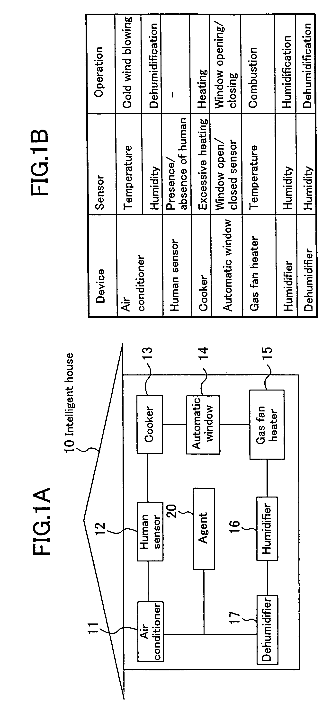
[0042] Embodiment 1 of the present invention will be descried by referring to devices installed in an intelligent house as an example. Herein, the intelligent house means a dwelling house in a condition that devices in the house are connected with each other through a network so as to enable information interchange among the devices. Each device is capable of obtaining information from the other devices and capable of using such information in an operation of its own.

[0043]FIG. 1 is a conceptual diagram illustrating an example of the intelligent house. FIG. 1 indicates devices relating to control of living environment such as temperature and humidity in the house. In an actual intelligent house, various devices such as devices dealing with video or audio and devices relating to meals are installed besides the devices relating to the control of the living environment. However, only a partial configuration of the network in the intelligent house is shown in FIG. 1 conceptually for th...

embodiment 2

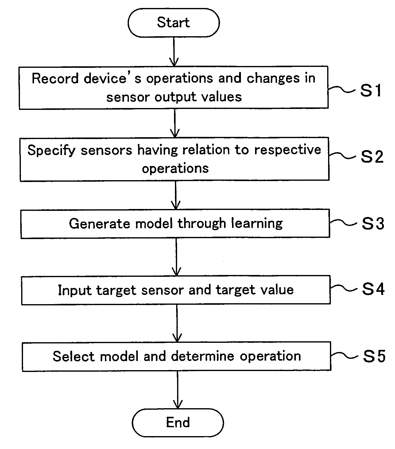
[0088] One of significant features in Embodiment 2 of the present invention lies in that in the step S5 in the flow of FIG. 4, a future change in output value of the target sensor is taken into consideration in the operation determination based on the prediction model obtained through learning.

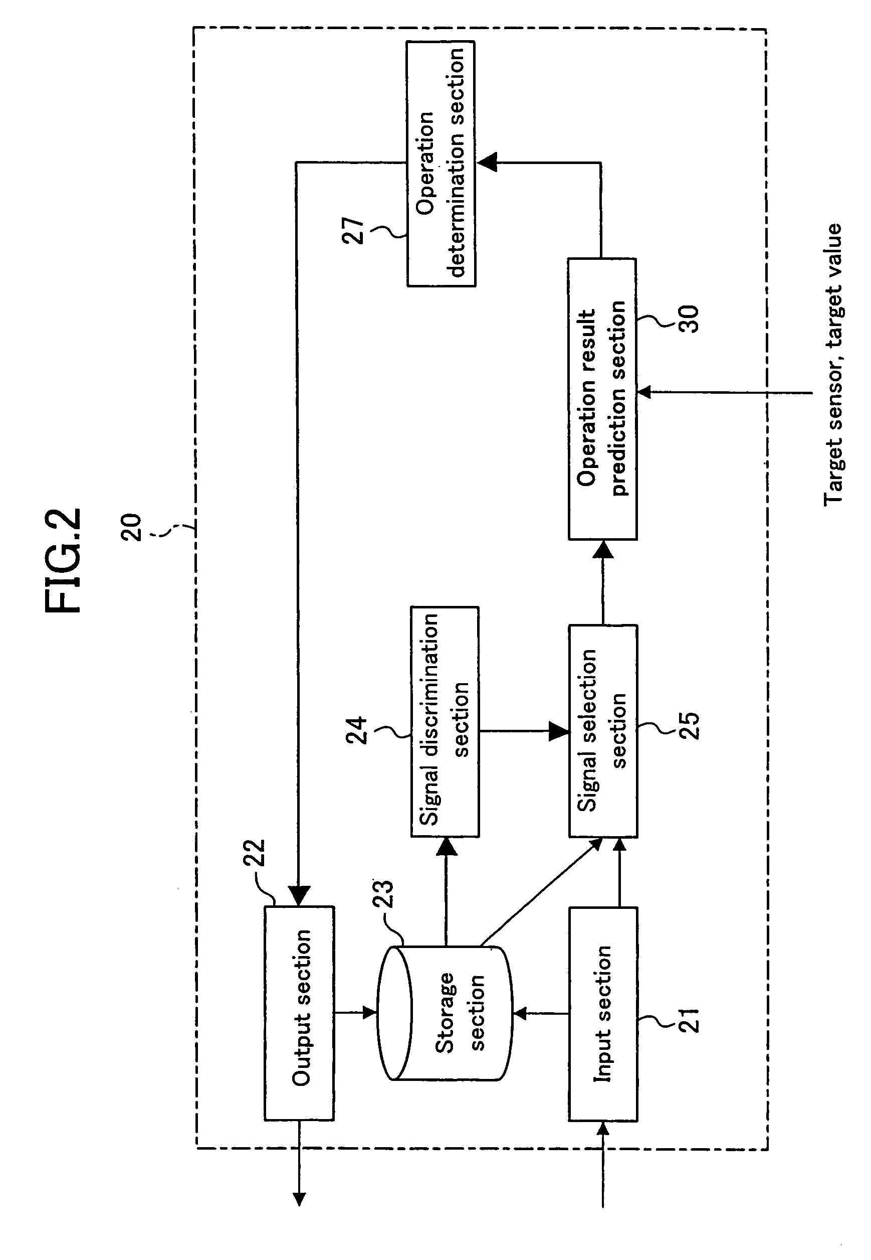
[0089]FIG. 12 shows a constitution of an agent 20A according to the present embodiment. In FIG. 12, the same reference numerals are assigned to constitutional elements common to those in FIG. 1, and the detailed description thereof is omitted here. Difference in constitution from FIG. 1 is that an environment prediction section 28 is provided for predicting a future change in output value of the target sensor which is caused due to a factor other than the corresponding operation of the device.

[0090] In the actual system, there is a case where prediction of an external factor is necessary for determining an operation. For example, in the example of the aforementioned intelligent house 10, the...

embodiment 3

[0093] The above embodiments reference an example of utilization in the intelligent house but the present invention is applicable to other use, for example, to generation of motion models of a home use robot.

[0094] A home use robot generally includes, as input sensors, a visual sensor for video input, an auditory sensor for speech input, a tactile sensor for detecting user's direct touch to the robot, a ultrasonic sensor for detecting a distance or an obstacle, encoders for detecting angles of joints, a sensor for detecting gravity movement, and the like. Further, it includes, as actuators for motion, a leg or a tire for transfer, a hand for moving an object, a head portion for expressing a viewing direction, nodding, and the like, a motor or a light for generating facial expressions, a speaker for speaking to the user, and the like. Particularly, a home use robot having a multifunction incorporates several tens of sensors for input and several tens of actuators for output, the num...


PUM


Abstract

A storage section stores various sensor signals obtained in an input section together with operation contents instructed in an output section. A signal discrimination section references the storage section to specify a sensor of which output value is influenced by a given operation. An operation result prediction section and an operation determination section generates through learning a prediction model expressing a relationship between the operation and the specified sensor and determines, with the generated prediction model referenced, an operation that allows an output of a target sensor to be a target value.

Description

CROSS REFERENCE TO RELATED APPLICATIONS [0001] This is a continuation of Application PCT / JP2005 / 003020 filed on Feb. 24, 2005. This Non-provisional application claims priority under 35 U.S.C. § 119(a) on Patent Application No. 2004-054155 filed in Japan on Feb. 27, 2004, the entire contents of which are hereby incorporated by reference.BACKGROUND ART [0002] 1. Field of the Invention [0003] The present invention relates to a technology of autonomous device control in a system having at least one device and a plurality of sensors, such as a home use robot, an information terminal, a home use device network in an intelligent house, and the like, and particularly relates to a technology of performing determination of device's operation through prediction. [0004] 2. Description of the Prior Art [0005] Recently, development in home use robots, information terminals, home use devices, and the like is progressing to have a multifunction. In these devices, numerous sensors for obtaining vari...

Claims


Application Information

Patent Timeline
IPC IPC(8): G05B11/01G05B13/02
CPCG05B13/027
Inventor MORIKAWA, KOJI
Owner PANASONIC CORP
Why Eureka
Try Eureka