Method for the introduction of an integrated predetermined rupture line in a planar expansive body

a predetermined rupture and planar expansion technology, applied in the direction of laser beam welding apparatus, transportation and packaging, vehicular safety arrangments, etc., can solve the problems of inability to generate a series of blind holes, inability to generate a line of determinate residual wall thickness in textile material, and inability to use laser methods. to achieve the effect of preventing the removal of small amount of material and preventing the overload of the detector

Inactive Publication Date: 2006-10-19
GRIEBEL MARTIN +2
View PDF14 Cites 14 Cited by
  • Summary
  • Abstract
  • Description
  • Claims
  • Application Information

AI Technical Summary

Benefits of technology

[0025] The object of the invention is met, in accordance with the invention, by a method for generating a predetermined breaking line in a one-layer planar extending article, having a working side and a decorative side comprising a material with an inhomogeneous material density distribution. He method comprises the steps of directing a laser beam bundle to the working side for removing material in its beam path and thereby generating holes that are invisible from the decorative side. The laser beam bundle and the planar extending article carrying out a relative movement with respect to one another so that the holes are generated in a row along the desired predetermined breaking line. The laser beam is switched off for a period of ti

Problems solved by technology

Production of predetermined breaking lines in airbag coverings represents a special case because of the high safety risk involved.
No methods employing a laser are known from the prior art for introducing a predetermined breaking line in airbag coverings with a textile or other decorative layer having an inhomogeneous material density distribution.
However, generating a line of determinate residual wall thickness in textile material is completely impossible because of the inhomogeneous material density distribution.
However, the Applicant of the present invention and owner of the patent DE 196 36 429 C1 has recognized that this method is not suitable for generating a series of blind holes for working inhomogeneous materials such as a woven material in which even a first laser pulse passing through between the thread structure could strike the detector at full output.
In many materials, however, the material penetration is visible not because the hole diameter is perceptible, but rather because of surface warping or discoloration due to melted material.
None of the methods mentioned above is suitable for working a decorative layer of inhomogeneous material such as woven material or an airbag covering with a decorative layer of this kind.
It is immed

Method used


Image

  • Method for the introduction of an integrated predetermined rupture line in a planar expansive body
  • Method for the introduction of an integrated predetermined rupture line in a planar expansive body

Examples


Embodiment Construction

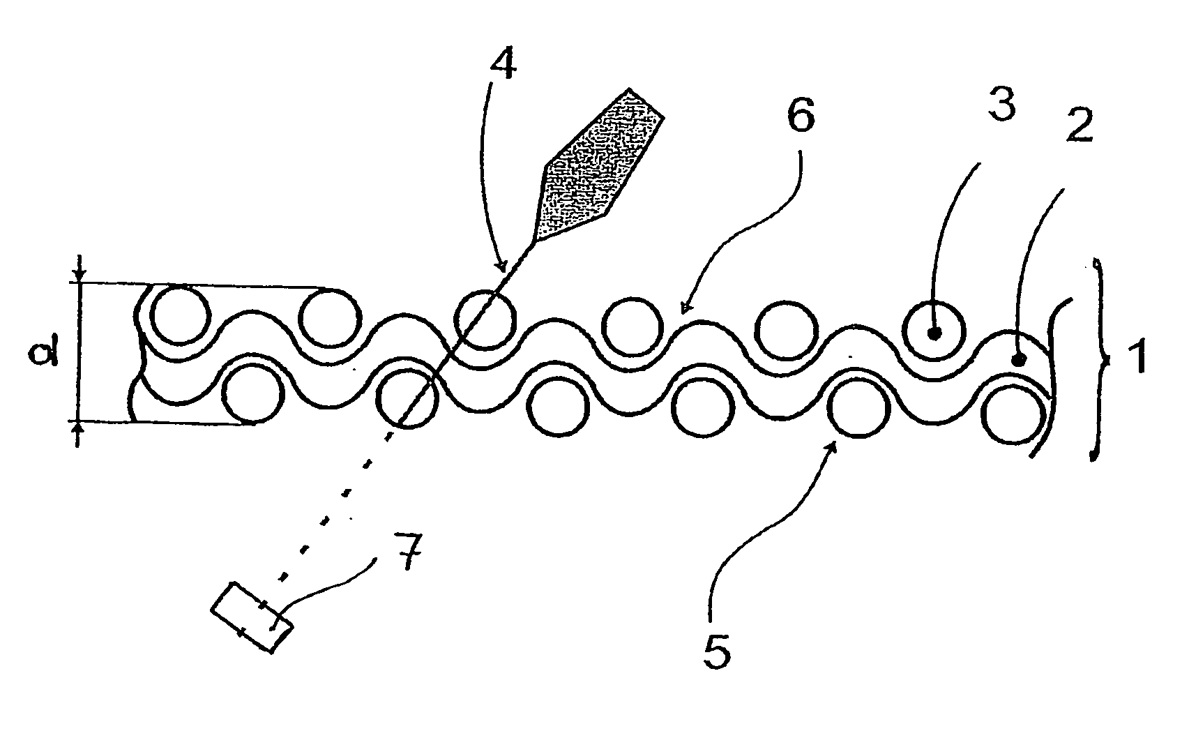
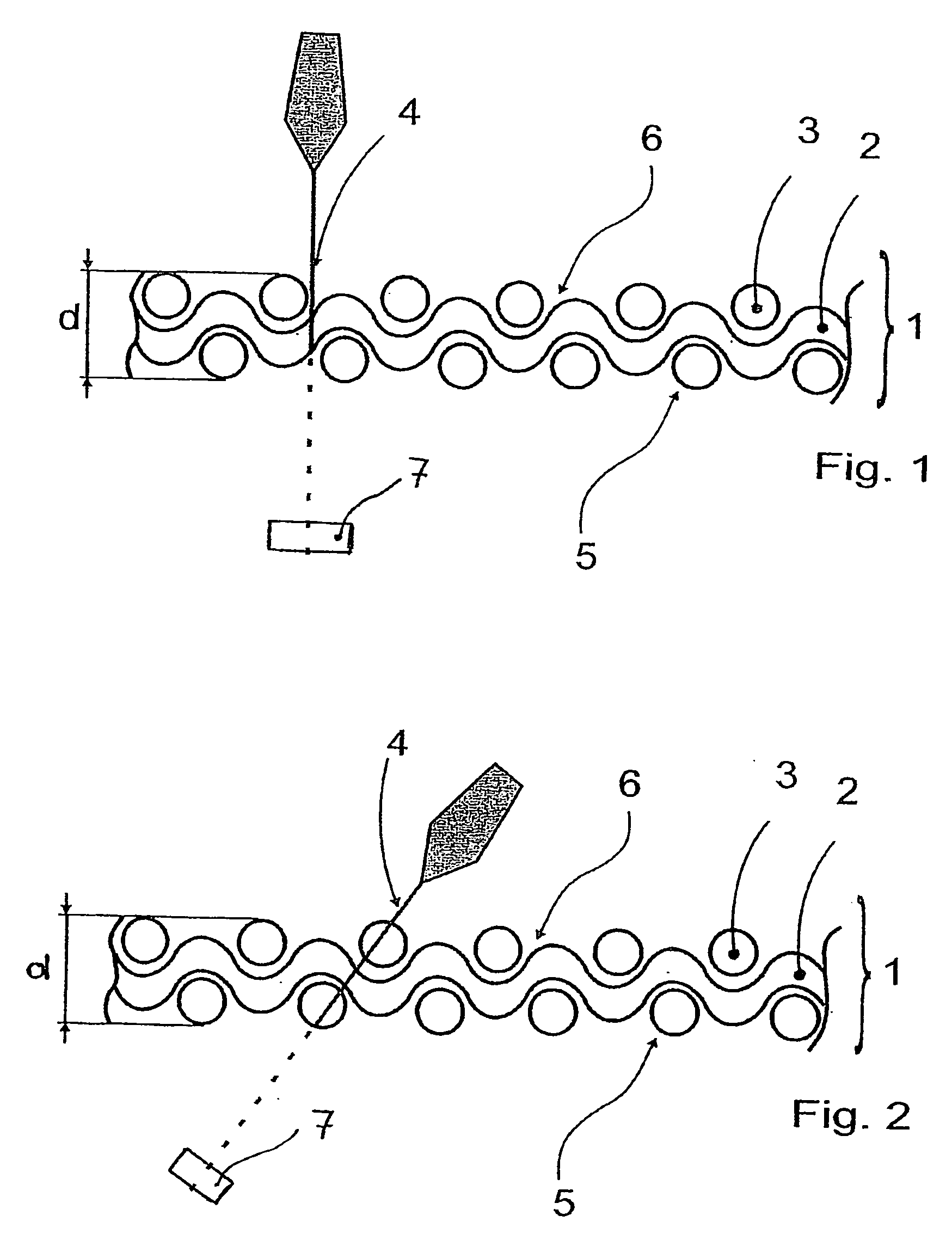
[0030] A first embodiment example shows the laser cutting of a woven material 1 comprising natural fibers. The material in question can be a covering material for a seat or the decorative layer for door paneling. FIG. 1 shows a section through a woven material 1 of this kind along a cross thread 2. A plurality of fibers bundled together forms a thread. A plurality of longitudinal threads 3 arranged next to one another are woven together with a plurality of cross threads 2 lying next to one another. The view in which the distances between the threads have been exaggerated clearly shows that a laser beam bundle 4, shown here as an individual beam, impinging on the woven material can penetrate the woven material 1 without striking a thread. At the other extreme, the laser beam bundle 4 could penetrate through the center of two threads lying on top of one another in another location. This means that although the woven material 1 has a substantially constant thickness d, the amount of ma...


PUM

PropertyMeasurementUnit
Angleaaaaaaaaaa
Lengthaaaaaaaaaa
Diameteraaaaaaaaaa

Abstract

The invention is directed to a method for introducing an integrated predetermined breaking line in a planar extending article. The method is particularly suitable for introducing an invisible predetermined breaking line with a reproducible, defined tearing resistance by means of a laser in an inhomogeneous material, such as a woven material, which can serve as the decorative layer of an airbag covering. According to the invention, the laser output is controlled depending upon the amount of material along the desired predetermined breaking line.

Description

CROSS-REFERENCE TO RELATED APPLICATION [0001] This application claims priority of International Application No. PCT / DE2003 / 003637, filed October 29, and German Application No. 102 54 377.1, filed Nov. 19, 2002, the complete disclosures of which are hereby incorporated by reference.BACKGROUND OF THE INVENTION [0002] a) Field of the Invention [0003] The invention is directed to a method for introducing an integrated predetermined breaking line in a planar extending article. The method is particularly suitable for introducing an invisible predetermined breaking line with a reproducible, defined tearing resistance by means of a laser in an inhomogeneous material such as a woven material. A method of this generic type is described in DE 196 36 429 C1. [0004] b) Description of the Related Art [0005] At the present time, it is common in many fields of application to introduce integrated predetermined breaking lines in planar extending articles in order to open these articles along this pre...

Claims


Application Information

Patent Timeline
IPC IPC(8): B23K26/38B23K26/03B60R21/2165
CPCB23K26/03B60R21/2165B23K2201/006B23K26/385B23K26/389B23K2101/006B60R21/201B23K2101/22
Inventor GRIEBEL, MARTINSTEINHAEUSER, FRANKPREUSS, NORBERT
Owner GRIEBEL MARTIN
Why Eureka
Try Eureka