Linear motor actuator

Active Publication Date: 2006-10-19
THK CO LTD
View PDF10 Cites 35 Cited by
  • Summary
  • Abstract
  • Description
  • Claims
  • Application Information

AI Technical Summary

Benefits of technology

[0017] Even when the formation pitch of the slots and teeth in the armature core is set to λn/4 (n is an integer), cogging that results from the positional relation between the armature core and the field magnet cannot be completely eliminated. In addition, as described above, cogging occurs in the sliders themselves due to the positional relation between them and the field magnet. In view of this, it is preferable that fixing means for fixing the sliders to the connecting top board be capable of freely changing a fixing position of the sliders to the connecting top board along the direction in which the table structure moves. With this construction, by performing fine adjustment on the fixing position of the armature with respect to the connecting top board along the movement direction of the table structure, it is possible to find the fixing position where the cogging that occurs due to the sliders and the cogging that occurs due to the armature core are canceled by each other. By fixing the armature to the connecting top board at such a position, cogging

Problems solved by technology

However, in the case of the linear motor actuators whose linear guide and linear motor are completely separated from each other as described above, it is extremely difficult and troublesome to perform the assembly while taking the above requirements into consideration.
For this reason, the above-mentioned assembly operation becomes even more difficult in the case where such a core-attached type linear motor is adopted.
Accordingly, when a large stroke length is set for the slider, this not only makes the preparation of the armature coil rather troublesome but also caus

Method used


Image

  • Linear motor actuator
  • Linear motor actuator
  • Linear motor actuator

Examples


Embodiment Construction

[0033] Hereinbelow, a linear motor actuator according to the present invention will be described in detail with reference to the accompanying drawings.

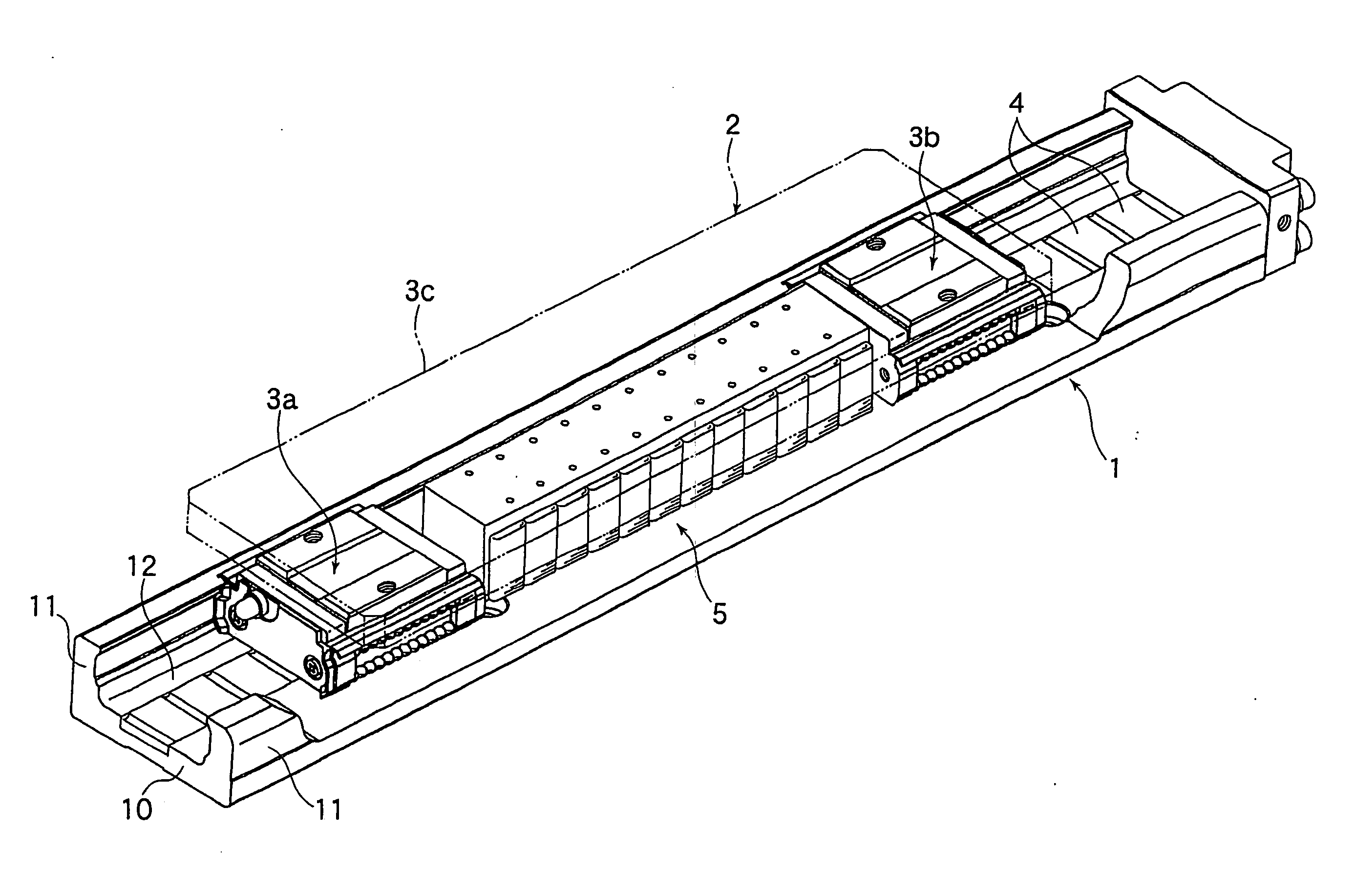
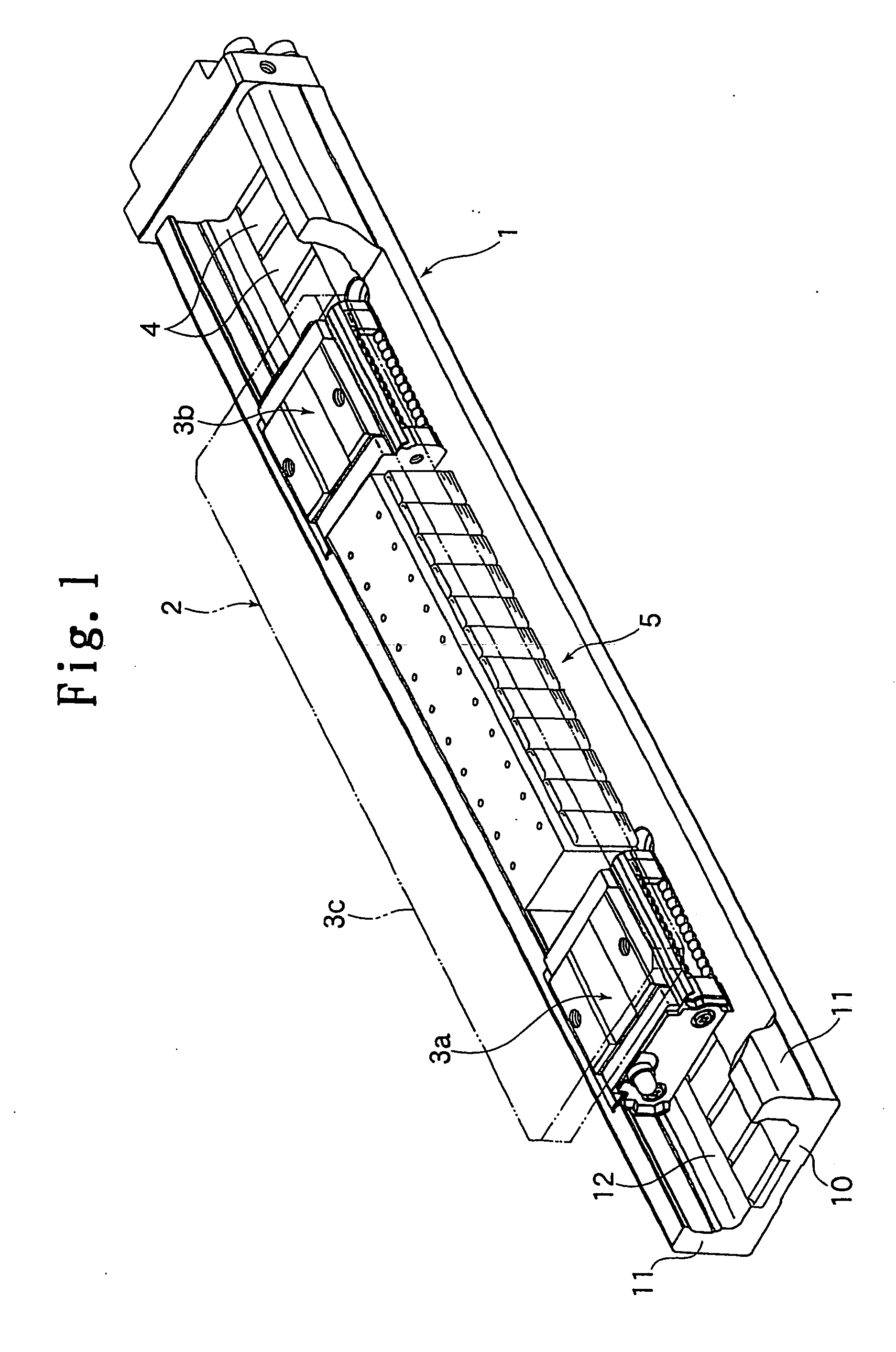
[0034]FIG. 1 shows a linear motor actuator according to a first embodiment of the present invention. The linear motor actuator is composed of: a track rail 1 formed in a channel-like configuration; a table structure 3 incorporating a movable member as the target control object and movable along the track rail 1; field magnets 4 arranged on the track rail 1; and an armature 5 mounted in the table structure 3 and constituting a linear motor together with the field magnets 4. By exciting the armature 5 mounted in the table structure 3, the table structure 3 can be propelled along the track rail 1 to be stopped at a predetermined position.

[0035] The track rail 1 has a stationary base portion 10 mounted to a stationary portion such as a bed by means of a bolt (not shown), and a pair of side wall portions 11, 11 extending upright from the...


PUM


Abstract

A track rail is formed in a channel-like configuration while having a guide passage for sliders. A table structure that moves within the guide passage includes:a pair of sliders that move forwards and backwards within the guide passage; and a connecting top board connecting those sliders to each other with a predetermined interval therebetween and provided with a mounting surface for a movable member. An armature constituting a linear motor is received between the pair of sliders, and field magnets constituting the linear motor are arranged in the track rail so as to face the guide passage. The armature and the field magnets, which constitute the linear motor, are completely integrated with the table structure and the track rail, which constitute a linear guide, and are entirely contained inside the linear guide.

Description

TECHNICAL FIELD [0001] The present invention relates to a linear motor actuator which supports a movable member such as a table on a stationary portion such as a bed by using a linear guide so that the movable member is free to reciprocate, the linear motor actuator being capable of repeatedly positioning the movable member with respect to the stationary portion by utilizing a propulsion force or brake force generated by a linear motor. More specifically, the present invention relates to an improvement for integrating the linear motor and the linear guide in a compact manner. BACKGROUND ART [0002] Linear actuators, which impart linear motion to a movable member such as a table and cause the movable member to stop at a predetermined position, are frequently used for various kinds of tables of machine tools, the moving portion of industrial robots, various kinds of conveying devices, and the like. Conventionally, with respect to the linear actuators of this type, known examples of dri...

Claims


Application Information

Patent Timeline
IPC IPC(8): H02K41/00H02K7/08F16C29/06H02K41/03
CPCF16C29/063H02K41/031H02K9/22H02K7/08F16C41/004H02K9/223H02K5/18
Inventor TERAMACHI, AKIHIROASO, TOSHIYUKITANAKA, YOSHINOBUKANESHIGE, HIROSHIXU, YUANIUN
Owner THK CO LTD
Why Eureka
Try Eureka