Electronic ballast for a lamp
- Summary
- Abstract
- Description
- Claims
- Application Information
AI Technical Summary
Benefits of technology
Problems solved by technology
Method used
Image
Examples
Embodiment Construction
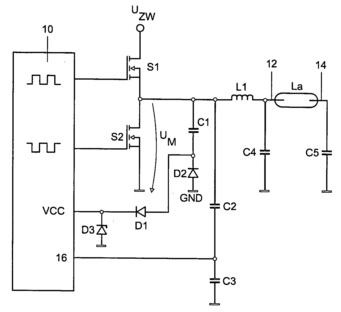
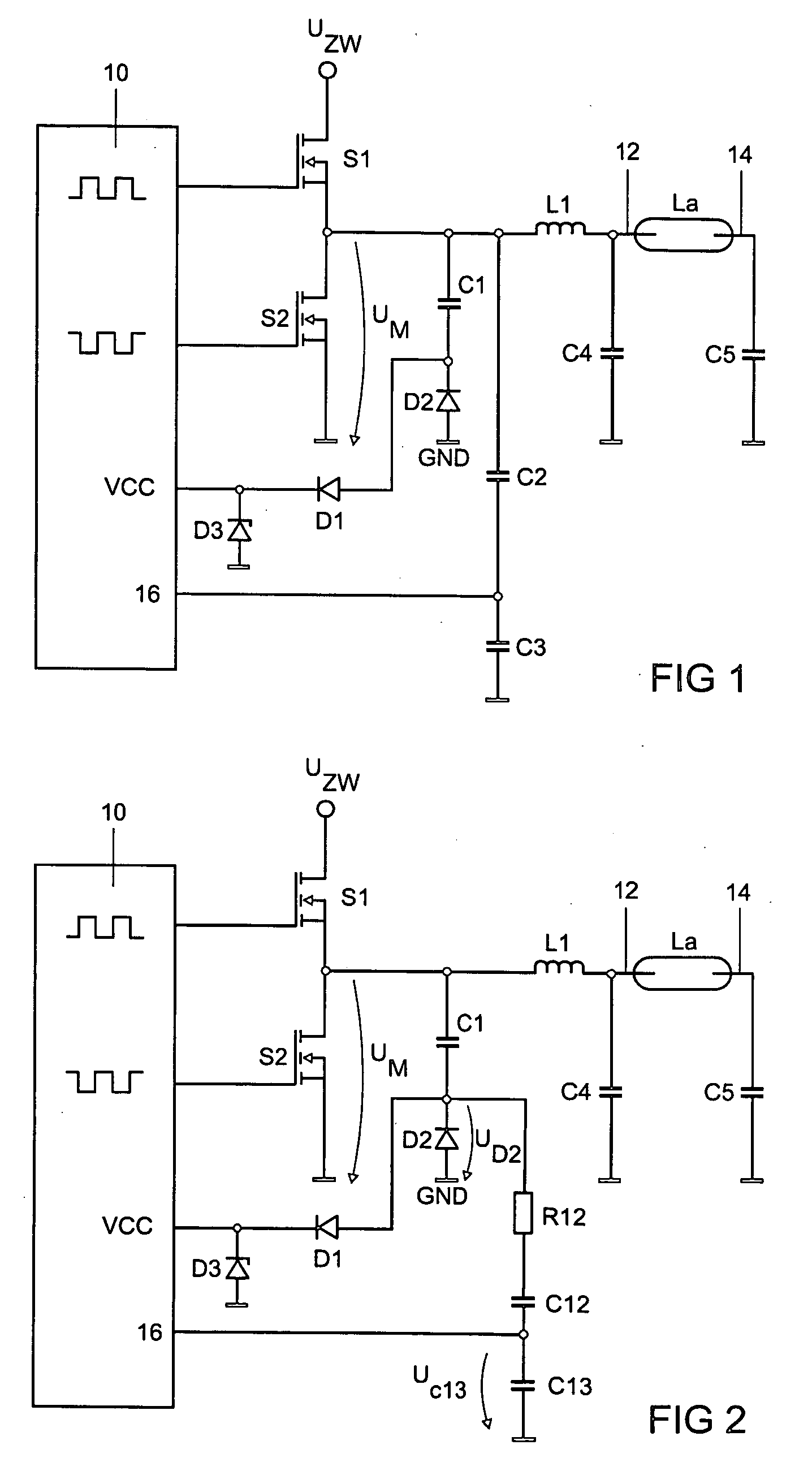
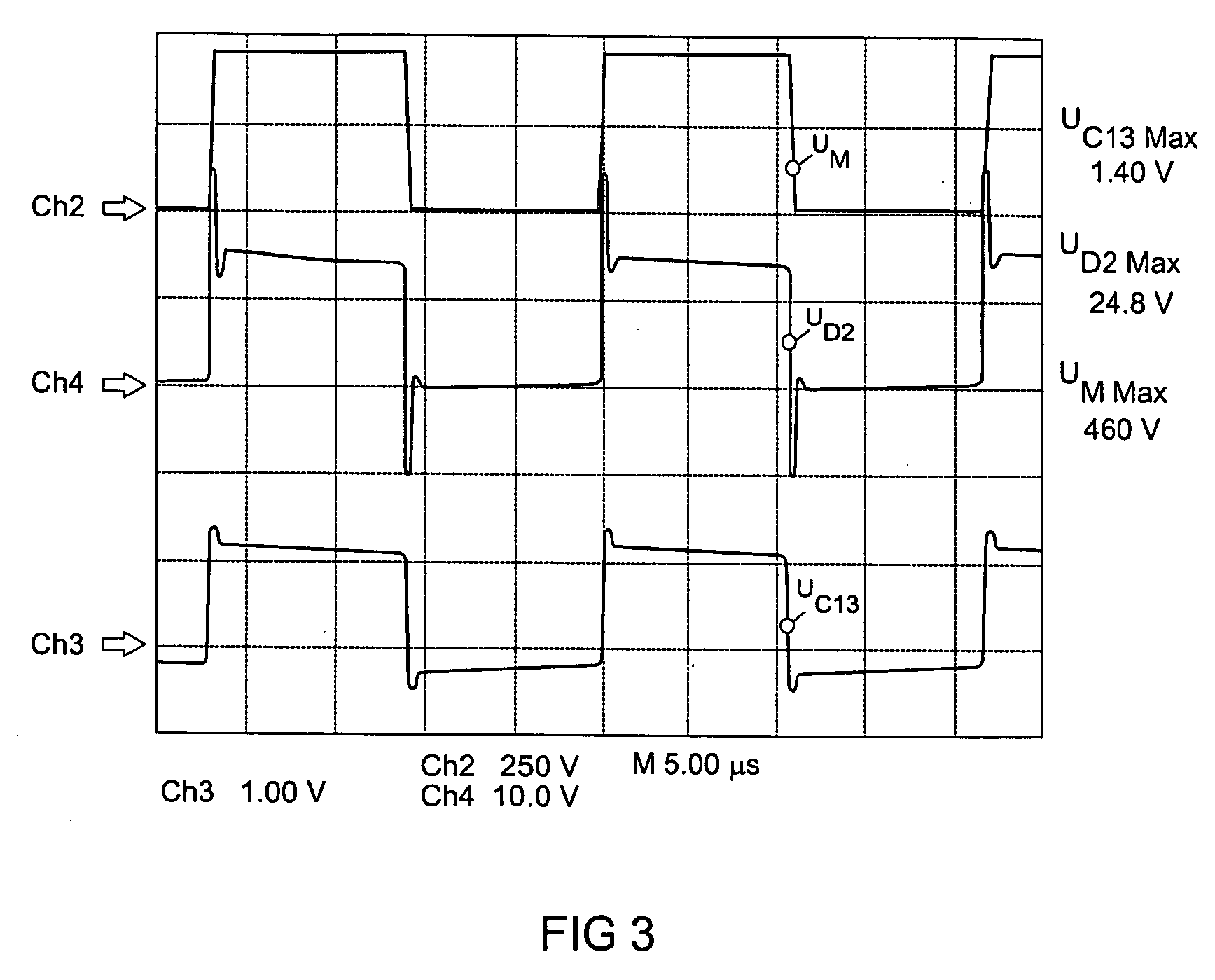
[0018]FIG. 2 shows a schematic illustration of a section from an electronic ballast according to the invention, in which the components, which correspond to those in FIG. 1, are characterized by the same references and are not introduced again. This circuit is characterized by the fact that the voltage UD2 at the connection point between the capacitor C1 and the diode D2 is used as the measurement signal for the purpose of identifying capacitive switching. In the exemplary embodiment illustrated, the diode D2 is connected to the ground potential. In this case, the voltage UD2 is applied to a capacitive voltage divider, which comprises the capacitors C12 and C13, the voltage UC13 across the capacitor C13 being applied to the input 16 of the control unit 10. The voltage UD2 can also be applied,. after conditioning, to the input 16 of the control unit 10 in another manner, for example using a resistive voltage divider. The resistor R12, which is connected between the connection point o...
PUM
 Abstract
Description
Claims
Application Information
 - R&D
- Intellectual Property
- Life Sciences
- Materials
- Tech Scout
- Unparalleled Data Quality
- Higher Quality Content
- 60% Fewer Hallucinations
Browse by: Latest US Patents, China's latest patents, Technical Efficacy Thesaurus, Application Domain, Technology Topic, Popular Technical Reports.
© 2025 PatSnap. All rights reserved.Legal|Privacy policy|Modern Slavery Act Transparency Statement|Sitemap|About US| Contact US: help@patsnap.com


