Three-dimensional display using variable focal length micromirror array lens

Active Publication Date: 2006-10-19
STEREO DISPLAY
View PDF80 Cites 20 Cited by
  • Summary
  • Abstract
  • Description
  • Claims
  • Application Information

AI Technical Summary

Benefits of technology

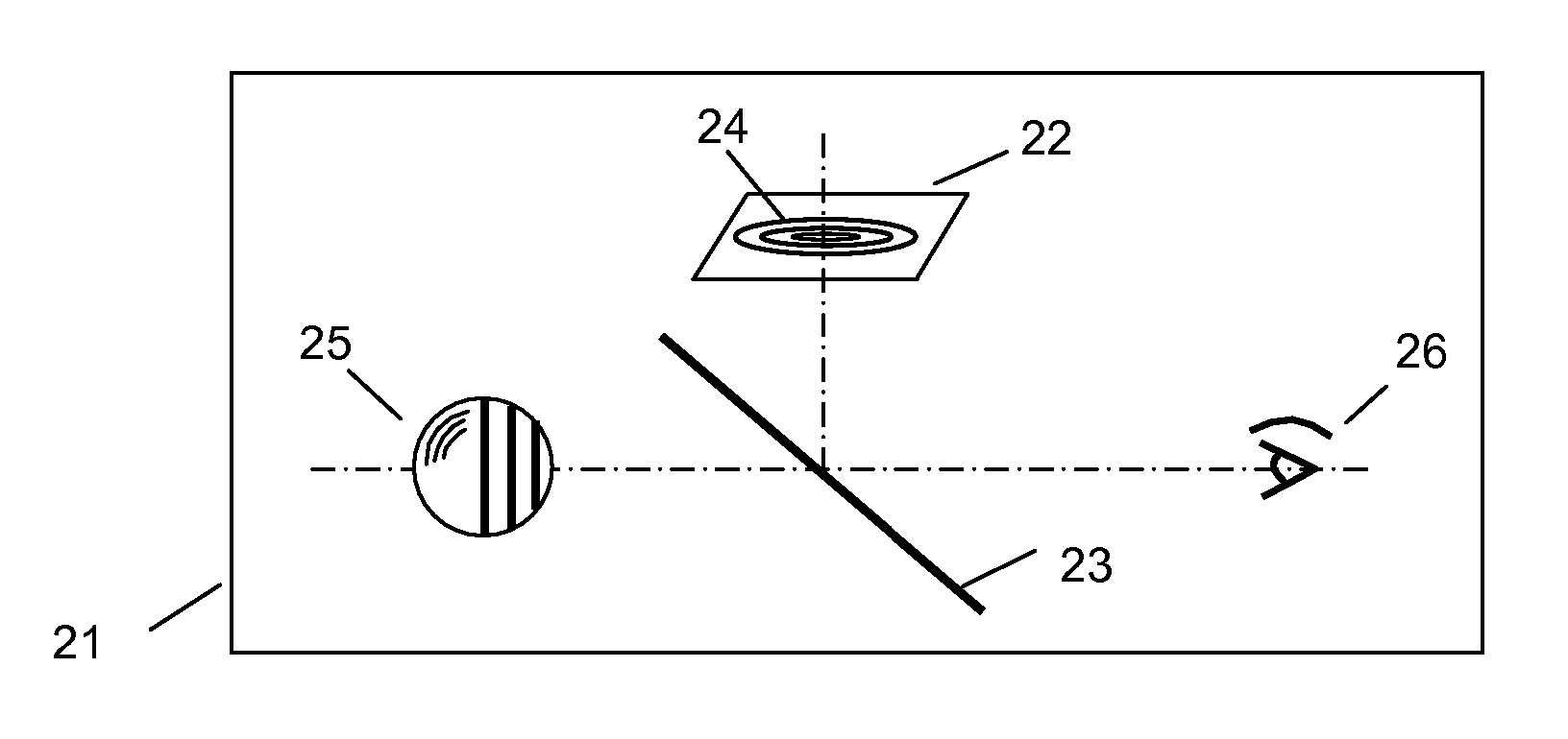
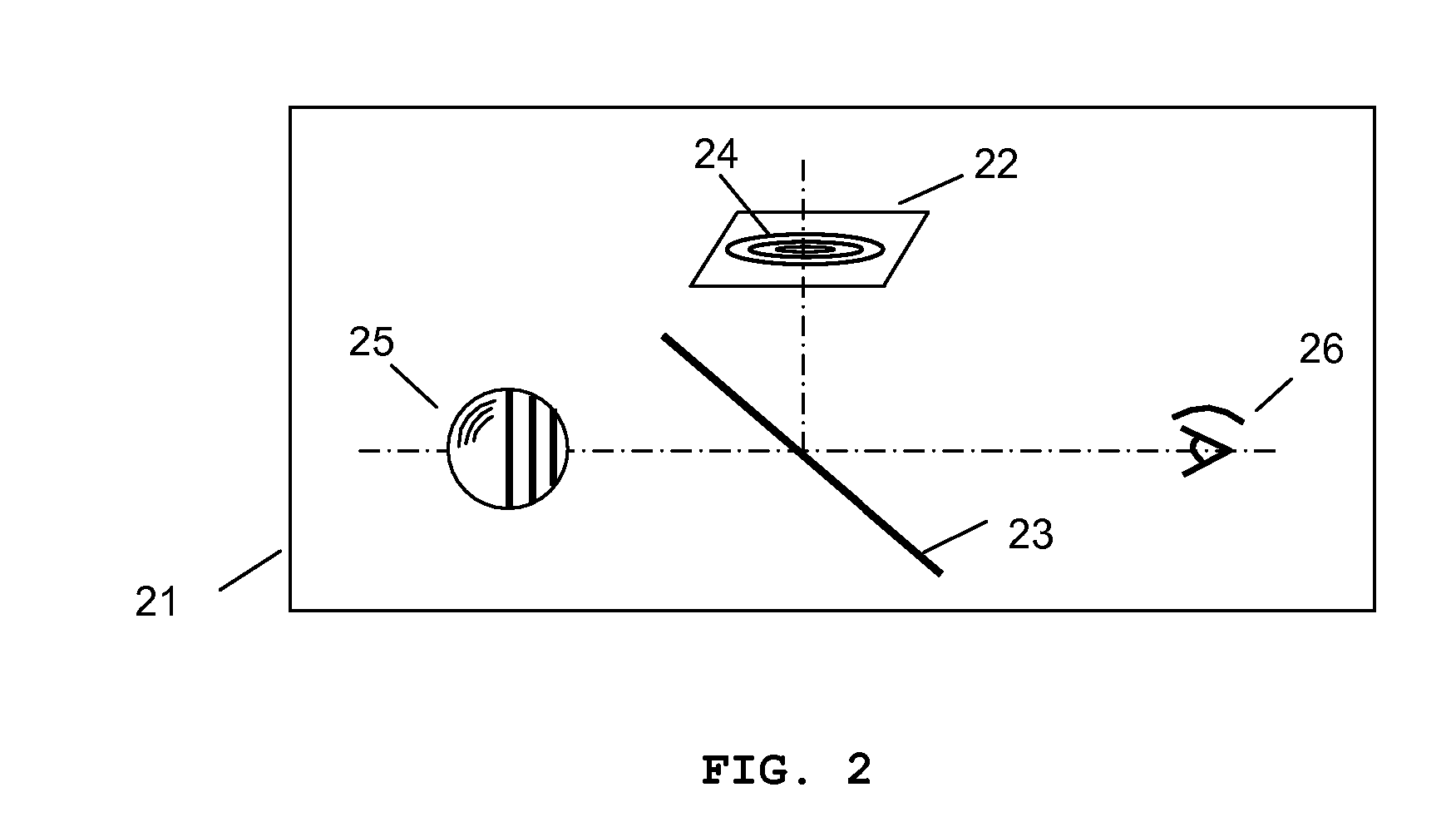
[0017] The two-dimensional display displays one depthwise image at a time, and the variable focal length MMAL receives light from the two-dimensional display and forms a corresponding image of each depthwise image at the required location in space using depth information of the depthwise image by changing the focal length of the variable focal length MMAL. The image formed by the variable focal length MMAL is located at the corresponding depth along the surface normal direction of the three-dimensional display screen, which is defined as a three-dimensional image display direction. The location of the image formed in space is adjusted by changing the focal length of the variable focal length MMAL, which is synchronized with the two-dimensional display so that the variable focal length MMAL can have a focal length corresponding to the depth information of the depthwise image displayed in the two-dimensional display. As a set of depthwise images representing an object are sequentially displayed in the two-dimensional display, a three-dimensional image of the object is formed in space accordingly and perceived as three-dimensional by a viewer. The number of depthwise images representing the object at a given moment is defined as number of depths, which depends on the depth resolution requirement, the refresh rate of the two-dimensional display, and the focusing speed of the variable focal length MMAL, and may increase for a b

Problems solved by technology

This method does not actually generate a three-dimensional image in space.
Therefore, this method has disadvantages that various factors including arbitrary distribution of the viewer's position, binocular disparity due to deviations in the distance between the two eyes, vergence, fatigue accumulation in the eye, accommodation, the relative position change of the three-dimensional image due to viewer's movement, etc., are involved, and such factors must be considered in order to provide a proper three-dimensional display.
Holography has been used for three-dimensional image display very limitedly due to its technical complexity and high manufacturing cost.
Austin's display has a

Method used


Image

  • Three-dimensional display using variable focal length micromirror array lens
  • Three-dimensional display using variable focal length micromirror array lens
  • Three-dimensional display using variable focal length micromirror array lens

Examples


Embodiment Construction

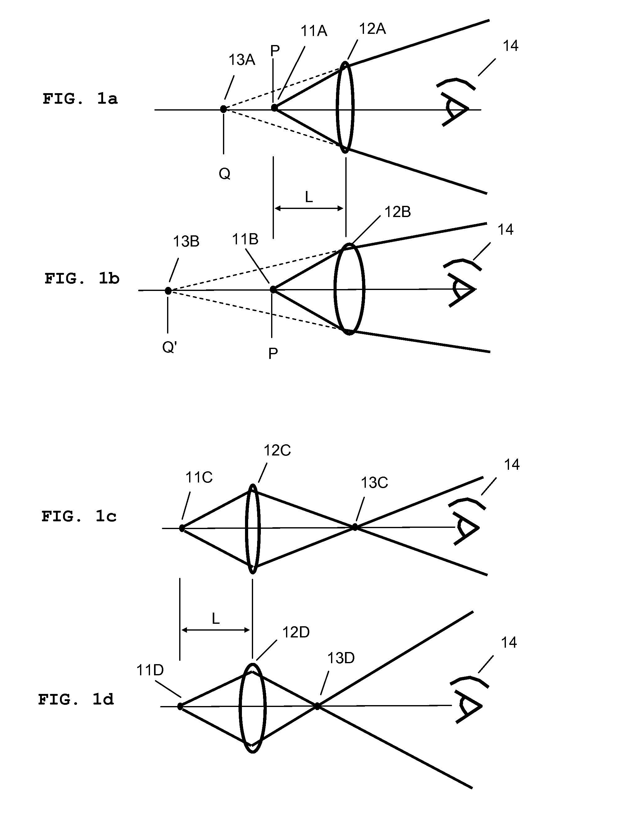
[0043]FIG. 1 illustrates the general principle regarding the distance or depth of an image formed by a lens, and the focal length of the lens. When the light from an object passes through a lens, it converges or diverges depending on the distance L between the object and the lens, and the focal length of the lens. In the description of the present invention, a lens means an optical element that focuses light, and is not confined to a refractive type lens.

[0044]FIG. 1a shows that the light from an object 11A passes through a lens 12A and then diverges at a different angle. FIG. 1b is a similar diagram for a lens 12B having a shorter focal length. The light refracted by the lenses 12A and 12B forms virtual images 13A and 13B, respectively. When a viewer 14 sees the refracted light, the viewer perceives objects 11A and 11B, which is positioned at point P, as existing at points Q and Q′, respectively.

[0045]FIG. 1c shows that the light from an object 11C passes through a lens 12C and t...


PUM


Abstract

A three-dimensional display device includes a two-dimensional display displaying a depthwise image, and a variable focal length micromirror array lens receiving light from the two-dimensional display and forming a corresponding image in the required location in space. Each depthwise image represents a portion of an object or scene having the same image depth, and the two-dimensional display displays one depthwise image at a time. The focal length of the variable focal length micromirror array lens changes according to the depth of the depthwise image being displayed. The variable focal length micromirror array lens has enough speed and focusing depth range for the realistic three-dimensional display.

Description

REFERENCE TO RELATED APPLICATIONS [0001] This application is a continuation-in-part of, and claims priority to U.S. patent application Ser. No. 10 / 778,281 filed Feb. 13, 2004, U.S. patent application Ser. No. 10 / 855,554 filed May 27, 2004, U.S. patent application Ser. No. 10 / 855,715 filed May 27, 2004, U.S. patent application Ser. No. 10 / 855,287 filed May 27, 2004, U.S. patent application Ser. No. 10 / 857,796 filed May 28, 2004, U.S. patent application Ser. No. 10 / 857,714 filed May 28, 2004, U.S. patent application Ser. No. 10 / 857,280 filed May 28, 2004, U.S. patent application Ser. No. 10 / 872,241 filed Jun. 18, 2004, U.S. patent application Ser. No. 10 / 893,039 filed Jul. 16, 2004, U.S. patent application Ser. No. 10 / 887,536 filed Jul. 08, 2004, U.S. patent application Ser. No. 10 / 914,474 filed Aug. 09, 2004, U.S. patent application Ser. No. 10 / 983,353 filed Nov. 8, 2004, U.S. patent application Ser. No. 11 / 072,597 filed Mar. 4, 2005, U.S. patent application Ser. No. 11 / 072,296 filed...

Claims


Application Information

Patent Timeline
IPC IPC(8): G09G5/00
CPCG02B27/2292G02B26/0833G02B30/56
Inventor SEO, CHEONG SOOCHO, GYOUNG ILBAEK, SANG HYUNE
Owner STEREO DISPLAY
Why Eureka
Try Eureka