Method and a device for measuring the three dimension surface shape by projecting moire interference fringe

Inactive Publication Date: 2006-10-19
LIU LANG
View PDF6 Cites 6 Cited by
  • Summary
  • Abstract
  • Description
  • Claims
  • Application Information

AI Technical Summary

Benefits of technology

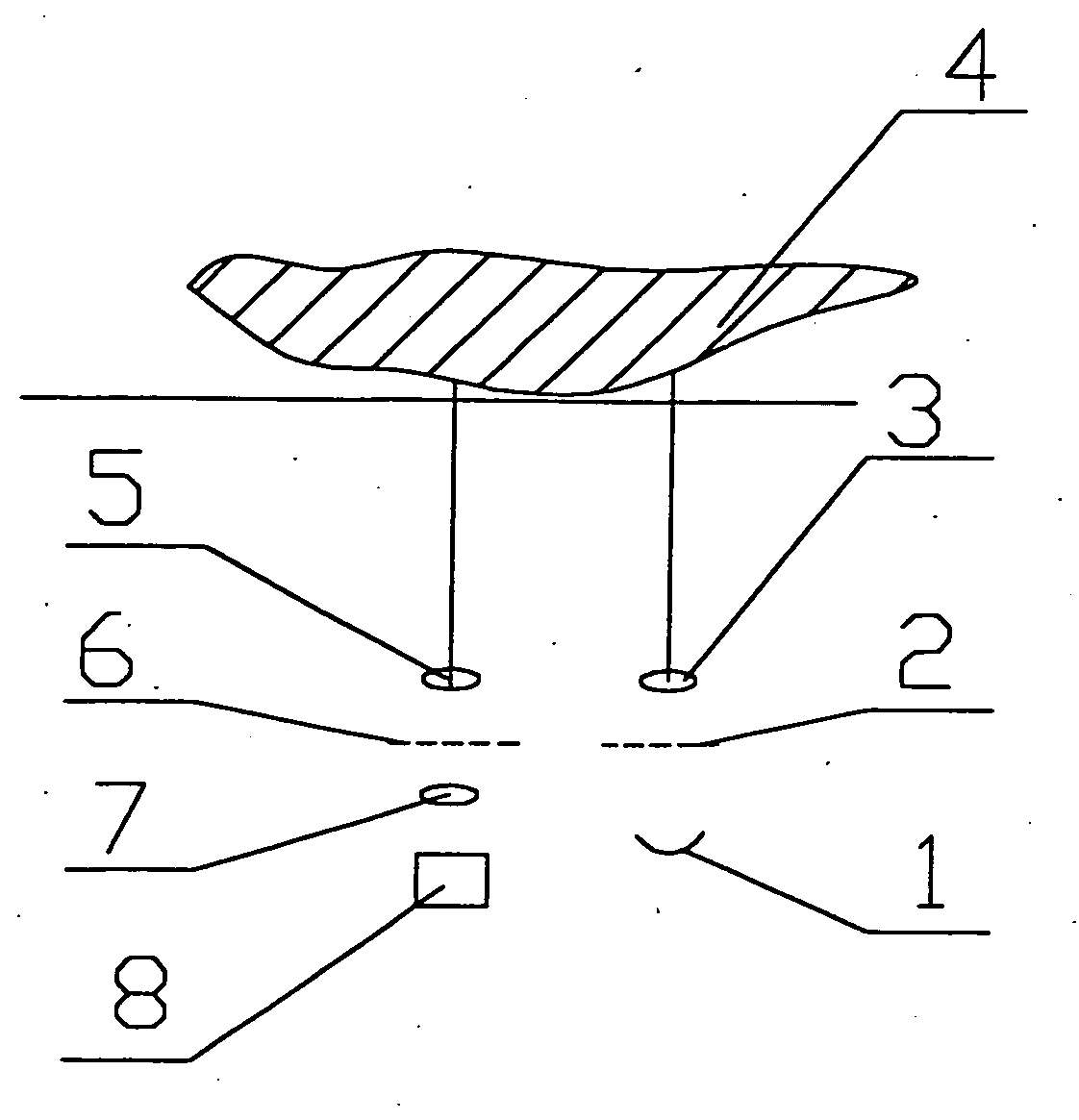
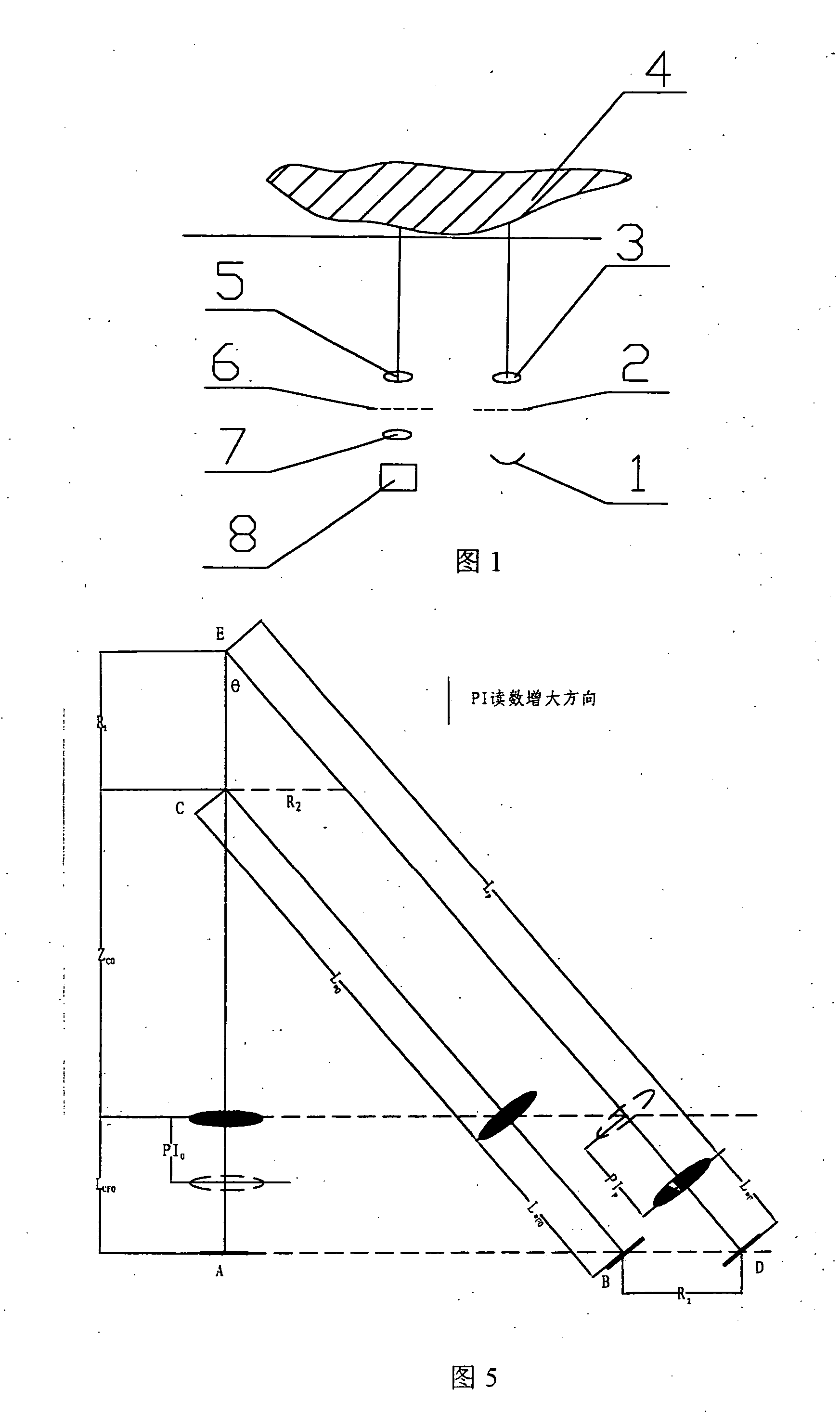
[0024] Namely, the first step is to form a right triangle using the mark point in the projection device, the mark point in the observation device and the mark point cast on the object surface by the projection device; measure projected object distance, projected image distance, observed object distance and observed image distance at some imaging position through two coordinate rectilinear motion axes and mark point in the projection device and observation device;

Problems solved by technology

3-D surface shape measuring is a hot issue that attracts attention in engineering and technology circles.
Given that contact force must be put on the object in mechanical probe scanning and that it takes time for numerical control

Method used


Image

  • Method and a device for measuring the three dimension surface shape by projecting moire interference fringe
  • Method and a device for measuring the three dimension surface shape by projecting moire interference fringe
  • Method and a device for measuring the three dimension surface shape by projecting moire interference fringe

Examples


Example

EMBODIMENT EXAMPLE 1

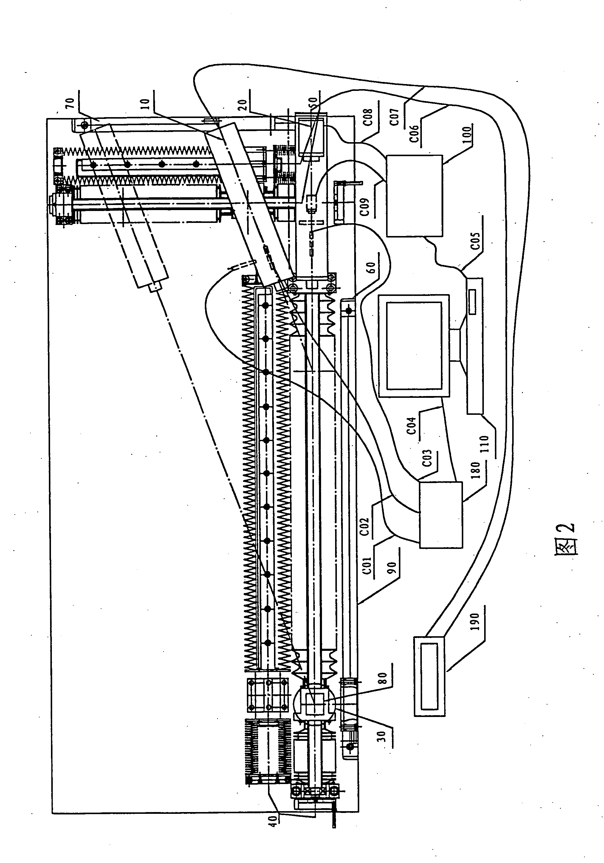
[0085] Showed as Chart 2, observation device 20 is fixed on the marble platform 90. Made by Japan THK Company and driven by a hand wheel, rectilinear motion axis 40 (comes with dust cover) with the length of 1,000 mm is fixed along the direction of the optical axis of observation device 20. Rotary stage 30 is fixed on the slider of the rectilinear motion axis and can make 360-degree rotation. The measured object, aviation engine blade 80 is fixed on the rotary stage 30. The first grating ruler 60 is fixed parallel with No. 1 rectilinear motion axis 40. Made by Japan THK Company and driven by a hand wheel, No. 2 rectilinear motion axis 50 (with dust cover) with the length of 400 mm is fixed vertically to No. 1 rectilinear motion axis 40. Projection device 10 is fixed on the slider of No. 2 rectilinear motion axis 50. The optical axis of projection device 10 and No. 2 rectilinear motion axis 50 are crossed as a γ angle. The second grating ruler 70 is fixed paralle...

Example

EMBODIMENT EXAMPLE 2

[0089] Showed as Chart 2, observation device 20 (observation device as shown in Chart 9) on the marble platform 90. Made by Japan THK Company and driven by a hand wheel, rectilinear motion axis 40 (comes with dust cover) with the length of 1,000 mm is fixed along the direction of the optical axis of observation device 20. Rotary stage 30 is fixed on the slider of the rectilinear motion axis and can make 360-degree rotation. The measured object, aviation engine blade 80 is fixed on the rotary stage 30. The first grating ruler 60 is fixed parallel with No. 1 rectilinear motion-axis 40. Made by Japan THK Company and driven by a hand wheel, No. 2 rectilinear motion axis 50 (comes with dust cover) with the length of 400 mm is fixed vertically to No. 1 rectilinear motion axis 40. Projection device 10 is fixed on the slider of No. 2 rectilinear motion axis 50. The optical axis of projection device 10 and No. 2 rectilinear motion axis 50 are crossed as a γ angle. The se...


PUM


Abstract

The invention discloses a method and device for measuring 3-D surface shape by projected moiré interference fringe. The said device includes a projection device for projecting mark point and main grating line, an observation device for receiving the mark point and grating line projected onto the object surface, and two-coordinates rectilinear motion axis. It uses the said two-coordinate rectilinear motion axis and the mark points of projection device and observation device to measure the projected object distance and the projected image distance in a certain imaging position; the observed object distance and the observed image distance; and determines the position of Zero-order fringe according to the mark point on the object; then determines the whole-field fringe order of the object surface by using phase-shift algorithm and unwrapping algorithm; finally accurately work out 3-D surface shape of the object according to the corresponding relationship between the deducted projected moiré interference fringe that takes a certain point on the object as the reference point and the object height.

Description

TECHNOLOGICAL FIELD [0001] The invention is about a 3-D surface shape measuring method and device, especially a measuring method and device for absolute measurement of 3-D surface shape by the principle of projected moiré interferometer. BACKGROUND TECHNOLOGY [0002] 3-D surface shape measuring is a hot issue that attracts attention in engineering and technology circles. The existing 3-D surface shape measuring methods include contact three-coordinates measuring machine and laser three-coordinates measuring machine. Contact three-coordinates measuring machine works through a mechanical probe driven by numerical control system scanning the surface of the measured object, and offers three-dimensional coordinates at every spot of the object. Its measurement accuracy may be above 0.01 mm. Given that contact force must be put on the object in mechanical probe scanning and that it takes time for numerical control system to move, Contact three-coordinates measuring machine is slow in measur...

Claims


Application Information

Patent Timeline
IPC IPC(8): G01B11/30G01B11/25
CPCG01B11/25
Inventor LIU, LANG
Owner LIU LANG
Why Eureka
Try Eureka