
Method and system for checking the position of a mechanical part with a light beam

Inactive Publication Date: 2006-10-19
MARPOSS SPA
View PDF1 Cites 17 Cited by
  • Summary
  • Abstract
  • Description
  • Claims
  • Application Information

AI Technical Summary

Benefits of technology

[0013] An object of the present invention is to provide a method and a system for checking the position of a tool, more specifically the cutting edge of a tool the profile of which is not known a priori, that is simple and reliable, overcoming the disadvantages that the known methods and systems present.
[0015] Among the advantages that the method according to the present invention and the associated system provide, there are the remarkable rapidity of the feasible checkings and the possibility of identifying—by means of the same apparatus and in an extremely simple and rapid way—the position of working areas of the tool, i.e. the points of the cutting edge oriented for performing machinings along different directions.

Problems solved by technology

Different applications of optical or optoelectronic systems for checking the position and / or the dimensions of non-rotating tools with profile not a priori precisely known present specific problems.
A specific problem rises whenever expensive and delicate devices with thick linear sensors that employ an equally thick light beam enabling to detect and to analyze the entire profile of the tool (for example “shadow-casting” systems) cannot be used and it is desired to utilize apparatuses in which there is simply detected the interruption of a light beam (for example a laser beam) with limited thickness.
The posed problem is to find the correct arrangement between tool and light beam that enables the former to interfere with the latter at the significative dimension to be checked, since the position of the significative dimension along the entire profile of the tool is not a priori known.
In many cases this possible solution is not applicable by reasons of insufficient room available.
Moreover such solution is not really flexible because it does not enable to carry out checkings of different tools—for example, tools mounted in different positions on the same turret—the significative profile of which, i.e. the profile that includes the cutting edge to be checked, lies in different planes.
Furthermore, the checkings that the solution disclosed U.S. Pat. No. 3,749,500 enables to perform are limited to a single direction along the significative profile plane, i.e. perpendicular to the light beam.
This known method may pose reliability problems bound to the selected scan interval, type of scan (greater or lesser number of points to be checked and consequent longer or shorter involved time) and consequent necessary processings.
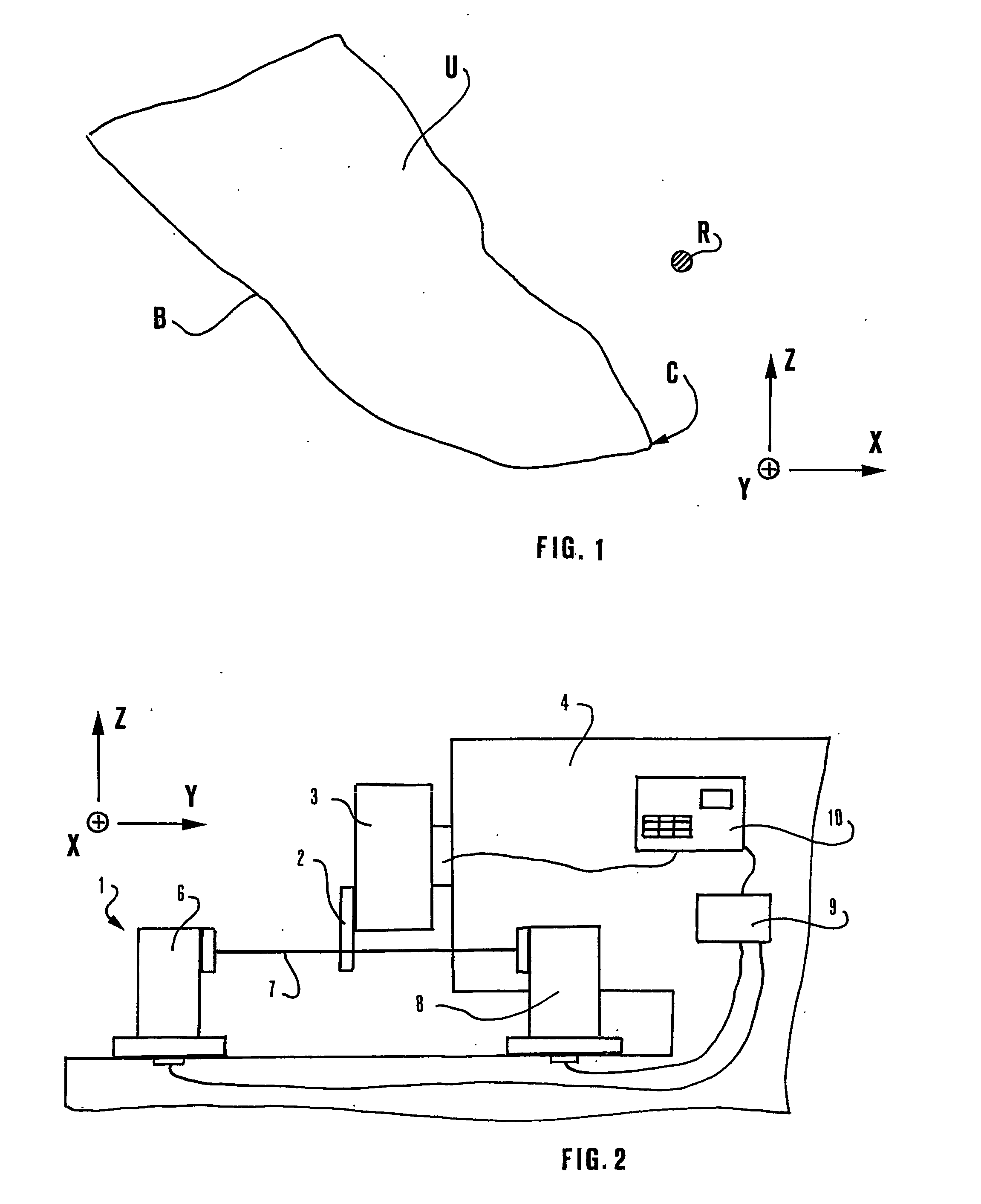
In fact, an inaccurate or incomplete detection of the profile may cause—in the formerly mentioned example—the missed identification of the point C of maximum projection in the direction X, the position of which has to be checked.
In any case, the known method is time consuming and involves complex processings.

Method used


Image

  • Method and system for checking the position of a mechanical part with a light beam
  • Method and system for checking the position of a mechanical part with a light beam
  • Method and system for checking the position of a mechanical part with a light beam

Examples


Embodiment Construction

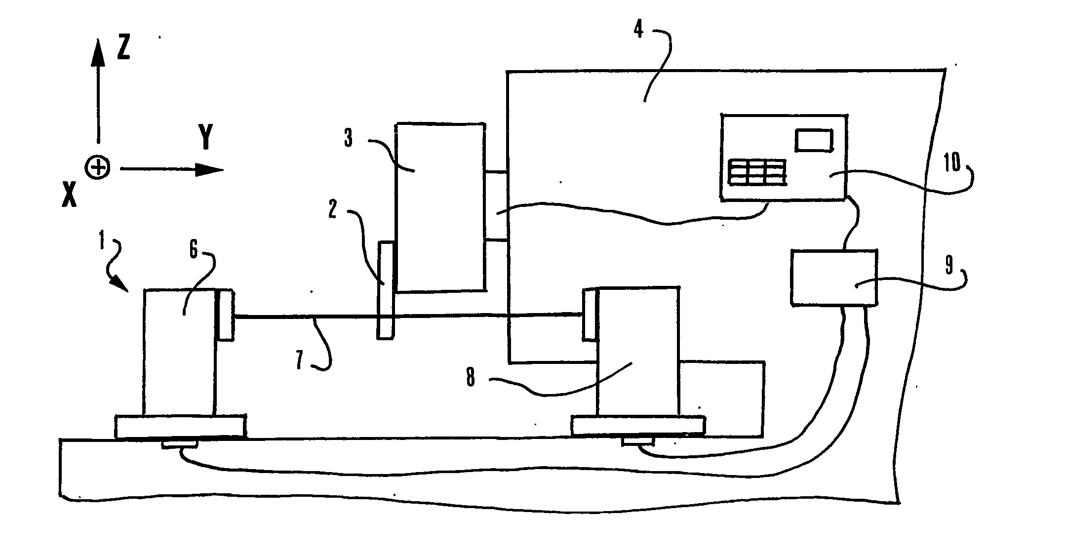
[0022]FIG. 2 illustrates, in an extremely schematic form, a checking system including an optoelectronic apparatus 1 in the course of checking a mechanical part 2, more specifically a tool located in a turret 3 of a lathe 4 to which the apparatus 1 is coupled. Typically, the turret 3 carries other tools, not shown in the schematic representation of FIG. 1. The apparatus 1 includes an emitter 6, i.e. a device for generating a light beam 7, for example a laser beam, along a transversal trajectory substantially parallel to direction Y, and a receiver 8, i.e. a sensor, arranged along said trajectory, that detects the correct reception of the light beam 7 or the non-reception of light owing to the interruption of the beam 7. A processing unit 9 is electrically connected to the emitter 6 and to the receiver 8. The system includes a control unit 10, connected to the processing unit 9, for controlling in a known way, by means of suitable activation devices also known and not illustrated in t...


PUM


Abstract

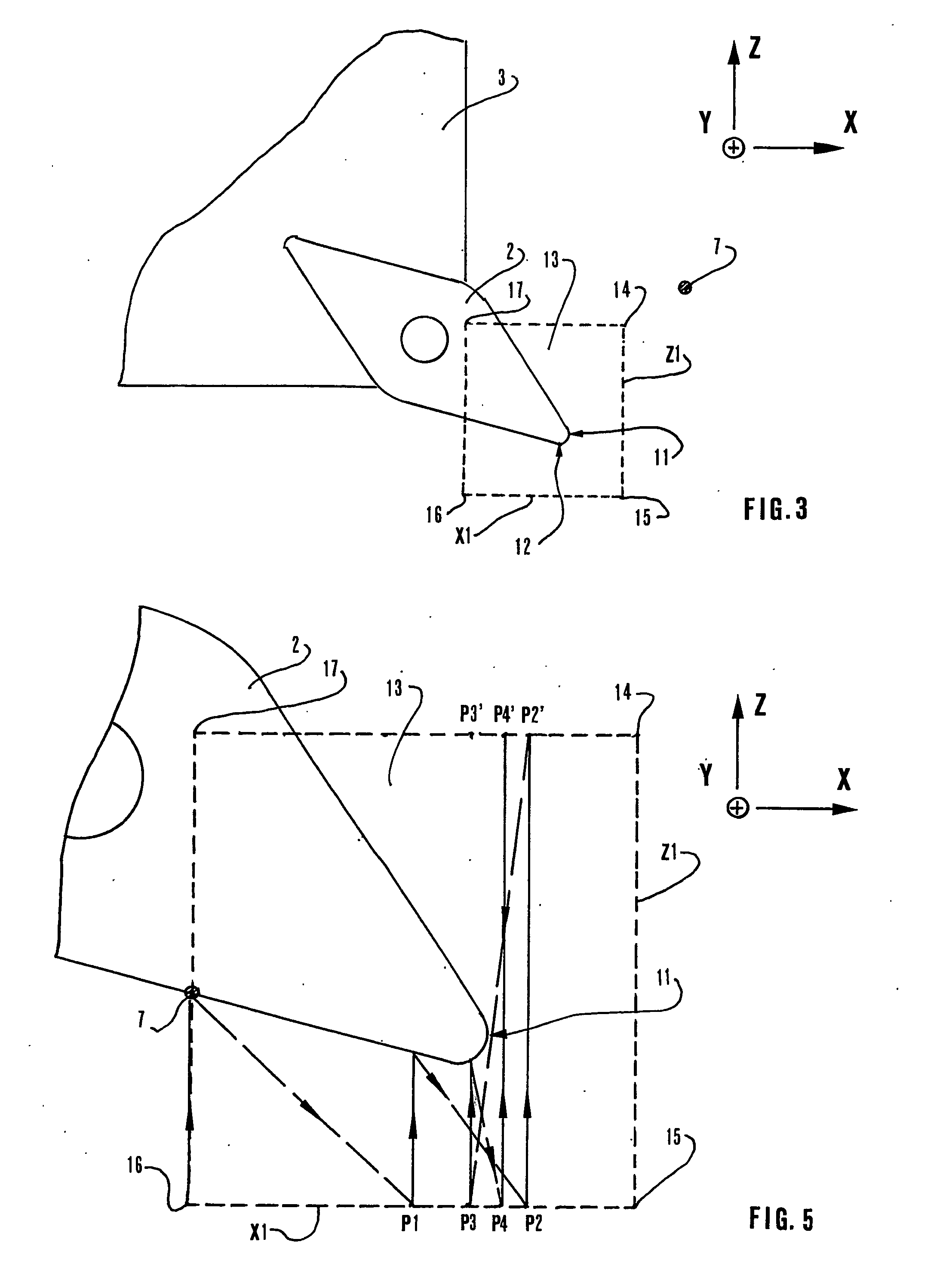
A method and a system for checking the position of a mechanical part (2), for example a tool of a lathe, along a checking direction (X), employs an optoelectronic device (1) with a laser beam (7) and a sensor (8) for detecting the interruption of the beam. Mutual displacements between the part to be checked and the optoelectronic device within a checking area (13) are controlled according to a sequence including linear inspection movements (30) along a direction (Z) perpendicular to the checking direction and at inspection positions (Pi;P1-P4). The inspection positions are spaced apart along the checking direction at progressively decreasing mutual distances (D), according to a sequence that converges to the searched position (PN).

Description

TECHNICAL FIELD [0001] The present invention relates to a method for checking the position of a mechanical part along at least one checking direction by means of an apparatus including a device for generating a light beam along a trajectory transversal to the checking direction, a sensor for detecting the interruption of the light beam, and devices for causing mutual displacements between the mechanical part and the light beam along the checking direction and along an inspection direction transversal to the checking direction. This invention also relates to a system for checking the position of a tool coupled to the turret of a machine tool. BACKGROUND ART [0002] Apparatuses for automatically checking the position or the integrity of tools are often utilized in machine tools of various types as, for example, numeric control machining centers where the condition of the tools can be checked in the course of the actual machining phase when the tool is coupled to the rotating spindle. [...

Claims


Application Information

Patent Timeline
IPC IPC(8): G01B11/14B23Q17/22B23Q17/24
CPCB23Q17/24B23Q17/22B23Q17/2428B23Q17/2452B23Q17/2457G05B19/401G05B19/4065G05B19/414
Inventor TURRINI, ANDREA
Owner MARPOSS SPA
Learn More