Electrical thermal overstress protection device

a protection device and thermal overstress technology, applied in the field of electrical equipment, can solve the problems of insufficient control speed or responsiveness for practical operations, and achieve the effect of increasing electrical resistan

Inactive Publication Date: 2006-10-19
REMY TECHNOLOGIES LLC
View PDF18 Cites 5 Cited by
  • Summary
  • Abstract
  • Description
  • Claims
  • Application Information

AI Technical Summary

Benefits of technology

[0007] An embodiment may also comprise remotely locatable overcrank protection device for use with a power source, a starter motor and an overload protection switch comprising: a main conductor member for transferring current from the power source to the starter motor; a parallel conductor member located separately from the main condu

Problems solved by technology

A problem with heat triggered devices such as bimetallic strips is that the degre

Method used


Image

  • Electrical thermal overstress protection device
  • Electrical thermal overstress protection device
  • Electrical thermal overstress protection device

Examples


Embodiment Construction

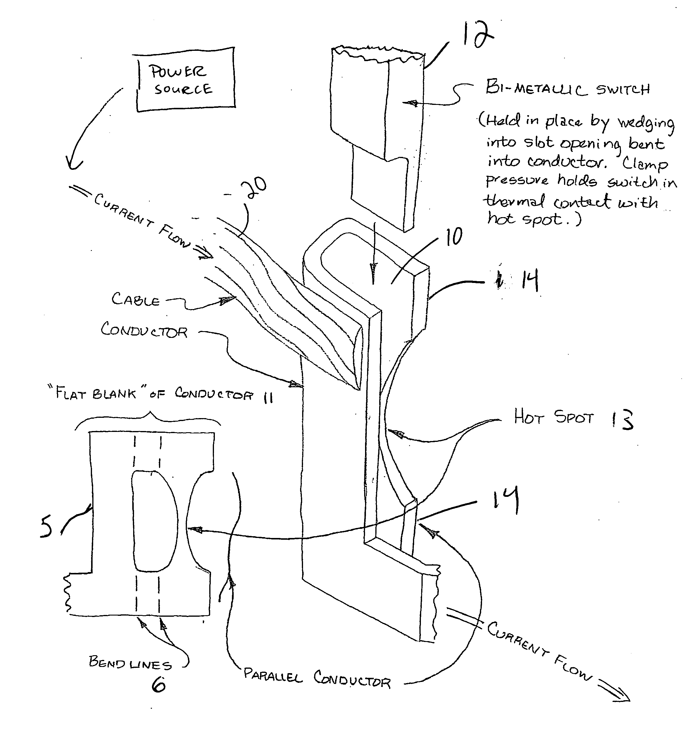
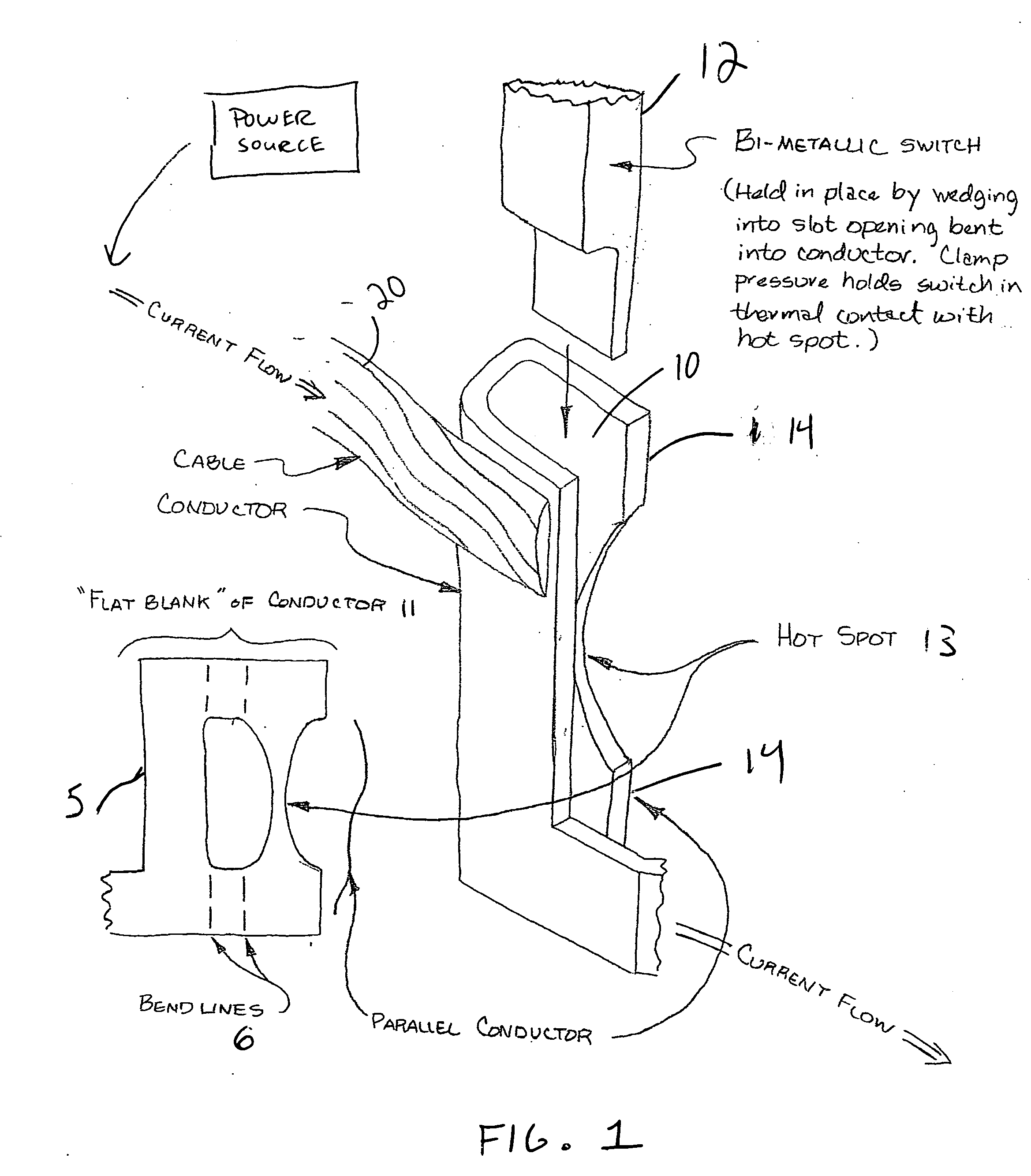
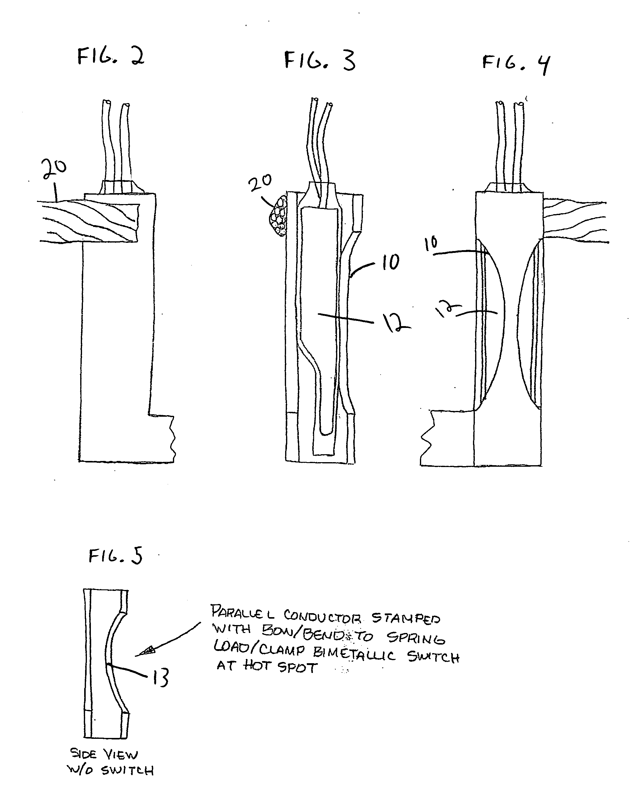
[0016] Referring to FIGS. 1-5, an exemplary embodiment having a parallel conductor member 10 is shown. As shown in FIG. 1, the parallel conductor member 10 is formed as an additional section of a flat blank conductor 11 when stamped or manufactured. In this embodiment, by bending the main conductor member 5 along bend lines 6, the parallel conductor member is bent into place to become located substantially parallel to the main conductor member 5. Cable 20 is connected to main conductor member 5 and the current flow is as shown. Thereafter, a bimetallic switch 12 is wedged into a frictional mounting between the two members as shown in FIGS. 1 and 3. The bimetallic switch is actuated from heat generated by electrical current traveling through the conductors. However, in the present embodiment, the parallel conductor member 10 creates a parallel electrical path to the existing current carrying conductor, i.e., main conducting member 5, within the machine or apparatus. An advantage of t...


PUM


Abstract

An electrical current overstress protection device for use with a power source and an overload protection switch comprising a main conductor member receiving current from the power source; a parallel conductor member connected to the main conductor member; and an area of localized increased electrical resistance located on the parallel conductor member and located proximate to the overload protection switch.

Description

TECHNICAL FIELD [0001] This application relates generally to an electrical apparatus. More specifically, this application relates to thermal overstress protection for an electrical machine. BACKGROUND [0002] Circuit breakers are known to use two-layer or bimetallic strips wherein due to one metal having different expansive properties than the other metal, the combined bimetallic strip will bend in an arc for example and disconnect a circuit when heated by overload current. [0003] A problem with heat triggered devices such as bimetallic strips is that the degree of control may not be fast enough or responsive enough for practical operations. Thus, a structure that has improved performance properties and improved responsiveness to heating and cooling is desirable. BRIEF SUMMARY OF THE INVENTION [0004] An embodiment may comprise an electrical current overstress protection device for use with a power source and an overload protection switch comprising a main conductor member receiving c...

Claims


Application Information

Patent Timeline
IPC IPC(8): H02H5/04
CPCH01H81/02H01H71/164
Inventor BRADFIELD, MICHAEL D.HUIBREGTSE, RICHARD W.
Owner REMY TECHNOLOGIES LLC
Why Eureka
Try Eureka