

Heating apparatus for x-ray inspection
a technology of x-ray inspection and heating apparatus, which is applied in the direction of ohmic-resistance heating, material analysis using wave/particle radiation, instruments, etc., can solve the problems of sample temperature drop, insufficient control of temperature, and inability to conduct accurate inspection, etc., to achieve high maintenance properties, high durability, and safe operation
Inactive Publication Date: 2011-04-28
ANBE YOSHINOBU
View PDF1 Cites 7 Cited by
- Summary
- Abstract
- Description
- Claims
- Application Information
AI Technical Summary
Benefits of technology
[0024]A second object of the present invention is to provide a heating apparatus for X-ray inspection equipped with a heater which is low in price, high in heat resistant temperature and long in service life.
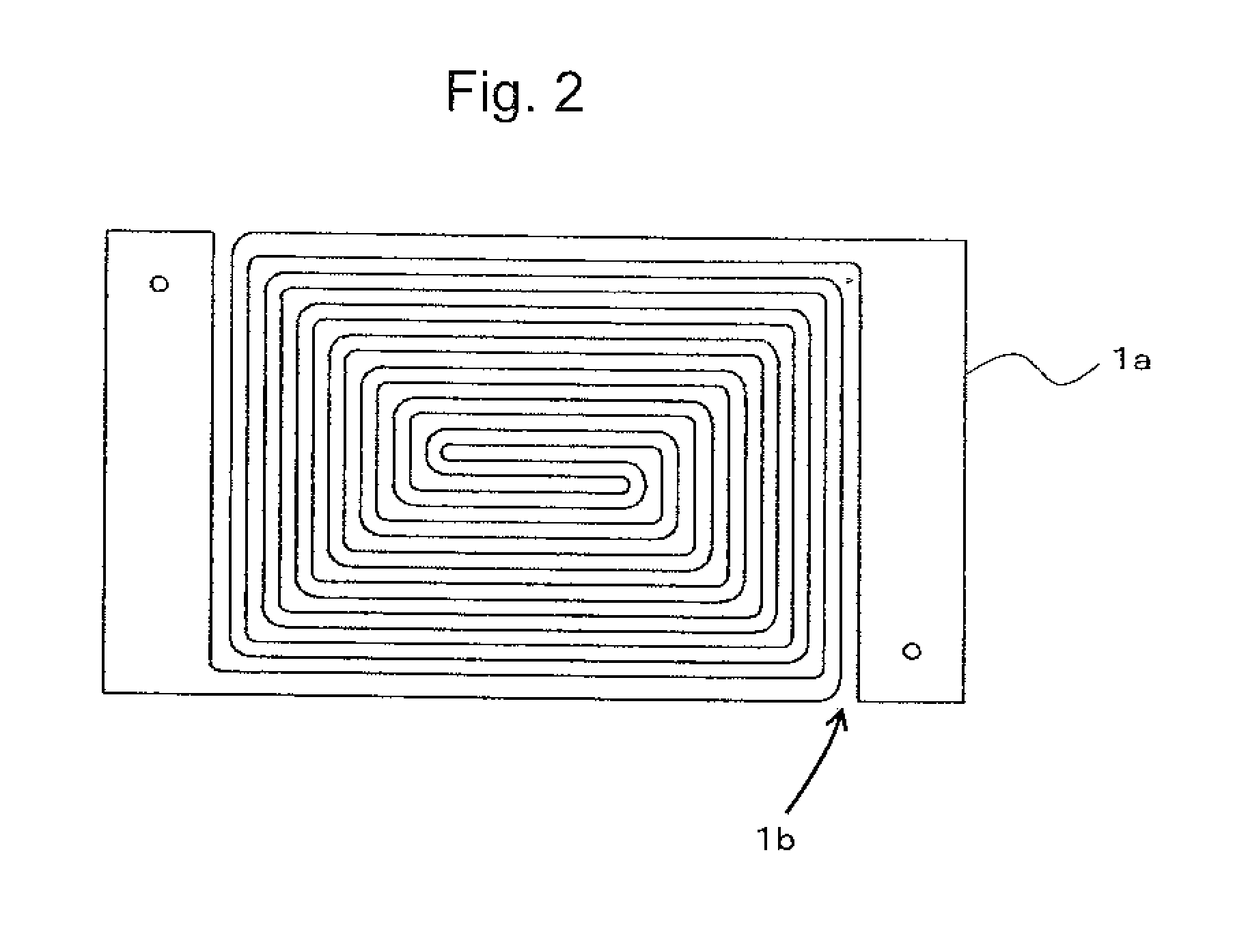
[0076]Further, as a matter of common knowledge, it was thought impossible in view of X-ray transmission to use a metal plate large in atomic weight as a heater. X-ray transmission properties of a metal can be simply expressed in a manner that the transmission properties are lower as the value obtained by multiplying an atomic number with the thickness is larger. As a realistic problem, a 30 μm-thick stainless steel plate of SUS 430 was processed into a spiral type and used as a heater experimentally. This heater was excellent and free of any problems with respect to X-ray transmission properties, sufficient in heating value and found to be long in service life. The plate is made thinner to enhance the X-ray transmission properties and increase the electric resistance and therefore can be used as a heater. Further, this heater is extremely low in cost and can be processed by etching or others and also high in heat resistant temperature and long in service life.
Problems solved by technology
Since the metal absorbs, reflects, diffracts or scatters X-rays, a disadvantage is found that an X-ray receiving apparatus is unable to sufficiently receive an X-ray from an X-ray irradiation apparatus to result in a failure of conducting an accurate inspection.
However, according to the above-described conventional technologies, there has been a problem that, where a sample heated outside an inspection system is set inside the inspection system and subjected to observation, the sample decreases in temperature or unevenness in temperature distribution during the setting, thus resulting in a failure of controlling the temperature sufficiently.
Further, there also has been a problem that a change in the state of the sample in association with a change in the temperature, for example, void occurrence on melting of solder or a change in a wet state, is unable to be observed accurately and in real time according to a required profile.
And, there also has been a problem that the metal blocks the field of view for observing an X-ray image to result in a failure of making a sufficient observation.
However, in the above-described method, it has been difficult to elevate the temperature of a sample rapidly and also difficult to heat the sample in its entirety uniformly, thereby it has been difficult to control the temperature of the sample, resulting in a failure of making an observation in real time according to a required profile.
Therefore, a problem is posed that a system is made larger to increase a focal length, by which it is impossible to observe a very small component clearly at high magnification.
There also have been problems that an angle for observation is limited, a system is complicated and fabricated with difficulty and the system is more likely to malfunction.
However, a problem is posed that a ceramics heater is slow in elevating temperatures, difficult in controlling temperatures, easily broken and low in durability.
Further, since the heating apparatus is not provided with a mechanism for generating air flow within it, there is found a problem that unevenness in temperature distribution inside the apparatus causes.
This is because, in most cases, components are loaded above and below a glass epoxy board (the back surface is not flat) and therefore thermal conduction heating is not usable.
However, there is a significant difference in soldering behavior between thermal conduction heating and convection heating which is actually conducted on the market.
Therefore, a problem is posed that an air compressing mechanism is needed to result in a larger and complicated apparatus.
Method used
View moreImage
Smart ImageViewing Examples

Examples
embodiment 1
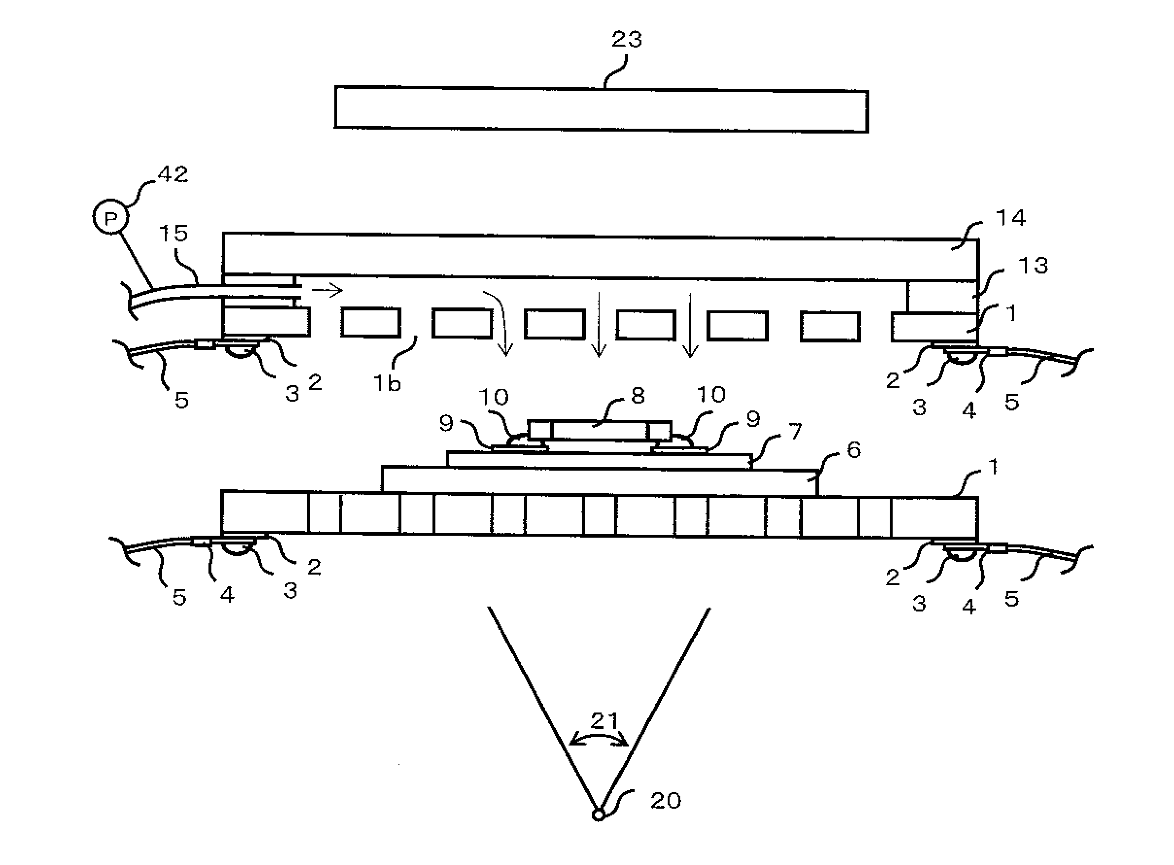
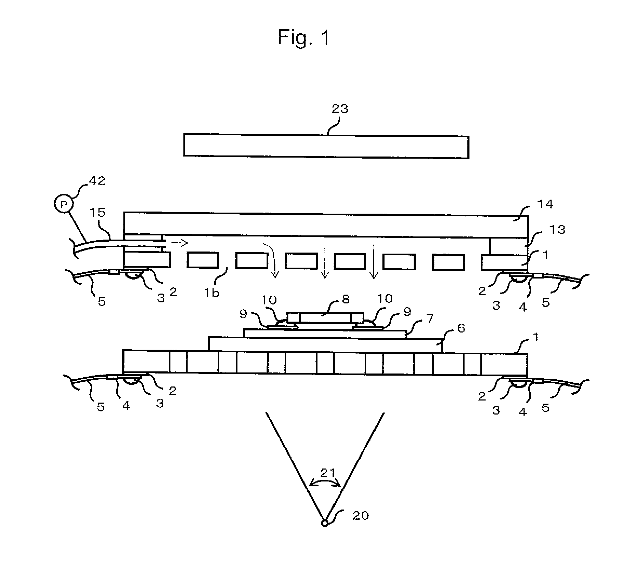
[0140]Planar heaters made of a carbon-fiber reinforced carbon composite material plate were disposed above and below and formed into the shape shown in FIG. 1. Then, they were used to fabricate a heating apparatus.
embodiment 2
[0141]Planar heaters made of a carbon-fiber reinforced carbon composite material plate were disposed above and below and formed into the shape shown in FIG. 9. Then, they were used to fabricate a heating apparatus.
embodiment 3
[0142]Planar heaters made of a carbon-fiber reinforced carbon composite material plate and ceramics plates were used to fabricate the heating apparatus shown in FIG. 10 and FIG. 16.
Login to View More PUM
| Property | Measurement | Unit |
|---|---|---|
| heat resistant temperature | aaaaa | aaaaa |
| temperature | aaaaa | aaaaa |
| shape | aaaaa | aaaaa |
Abstract
In a heating apparatus for X-ray inspection which heats at least one surface of a sample (7) by convection to perform an X-ray inspection, a planar heater 1 formed of an X-ray transmitting material having an opening 1b for passing gas is provided at a window part 22 for making an X-ray observation of the sample. Thereby, a board can be subjected to convection heating uniformly without enlarging or complicating the apparatus.
Description
TECHNICAL FIELD[0001]The present invention relates to a heating apparatus for X-ray inspection and, in particular, to a heating apparatus for X-ray inspection which is effectively used in analyzing a cause of defective generation at a solder joint part and capable of heating an object to be examined such as a sample to a target temperature or heating it according to a predetermined profile, thereby observing and recording the change in the state in real time.BACKGROUND ART[0002]In recent years, an assembled circuit board has been made high in density, large in the number of layers and increasing in variety of using materials. Therefore, the necessity for an X-ray inspection capable of observing the interior or joint part of a component, in addition to conventional optical inspections has increased.[0003]In particular, an X-ray inspection at high temperature capable of observing a change in crystalline structure or a change in the melted state by heating a sample to high temperatures...
Claims
Login to View More Application Information
Patent Timeline
 Patent Type & AuthorityApplications(United States)
IPC IPC(8): G01N23/02
CPCH05B3/283H05B2203/002H05B2203/003H05B2203/033H05B2203/017H05B2203/022H05B2203/004G01N23/02G01N23/20033H05B3/262
InventorANBE, YOSHINOBU
OwnerANBE YOSHINOBU