Electric circuit module as well as power converter and vehicle-mounted electric system that include the module

a technology of electric circuit modules and power converters, which is applied in the direction of dc-ac conversion without reversal, battery/fuel cell control arrangement, and semiconductor/solid-state device details, etc., can solve the problems of large heat capacity of converters including electric circuit modules and achieve high reliability, compact, and inexpensive

Inactive Publication Date: 2006-10-19
HITACHI LTD
View PDF17 Cites 106 Cited by
  • Summary
  • Abstract
  • Description
  • Claims
  • Application Information

AI Technical Summary

Benefits of technology

[0015] A recent problem imposed on electric appliances including electric circuit modules is to further make the electric appliances compact, inexpensive, and highly reliable. As for automobiles, for example, to make power converters including electric circuit modules compact, inexpensive, and highly reliable is an important problem. In other words, it is desired for automobiles to reduce the effect

Problems solved by technology

A recent problem imposed on electric appliances including electric circuit modules is to further make the electric appliances compact, inexpensive, and highly reliable.
As for automobiles, for example, to make power converters including electric circuit modules compact, inexpensive, and highly reliable is an important problem.
Therefore, to implement compact, inexpensive, highly reliable power converters is an important problem for automobiles.
When an electric appliance has an el

Method used


Image

  • Electric circuit module as well as power converter and vehicle-mounted electric system that include the module
  • Electric circuit module as well as power converter and vehicle-mounted electric system that include the module
  • Electric circuit module as well as power converter and vehicle-mounted electric system that include the module

Examples


embodiment 1

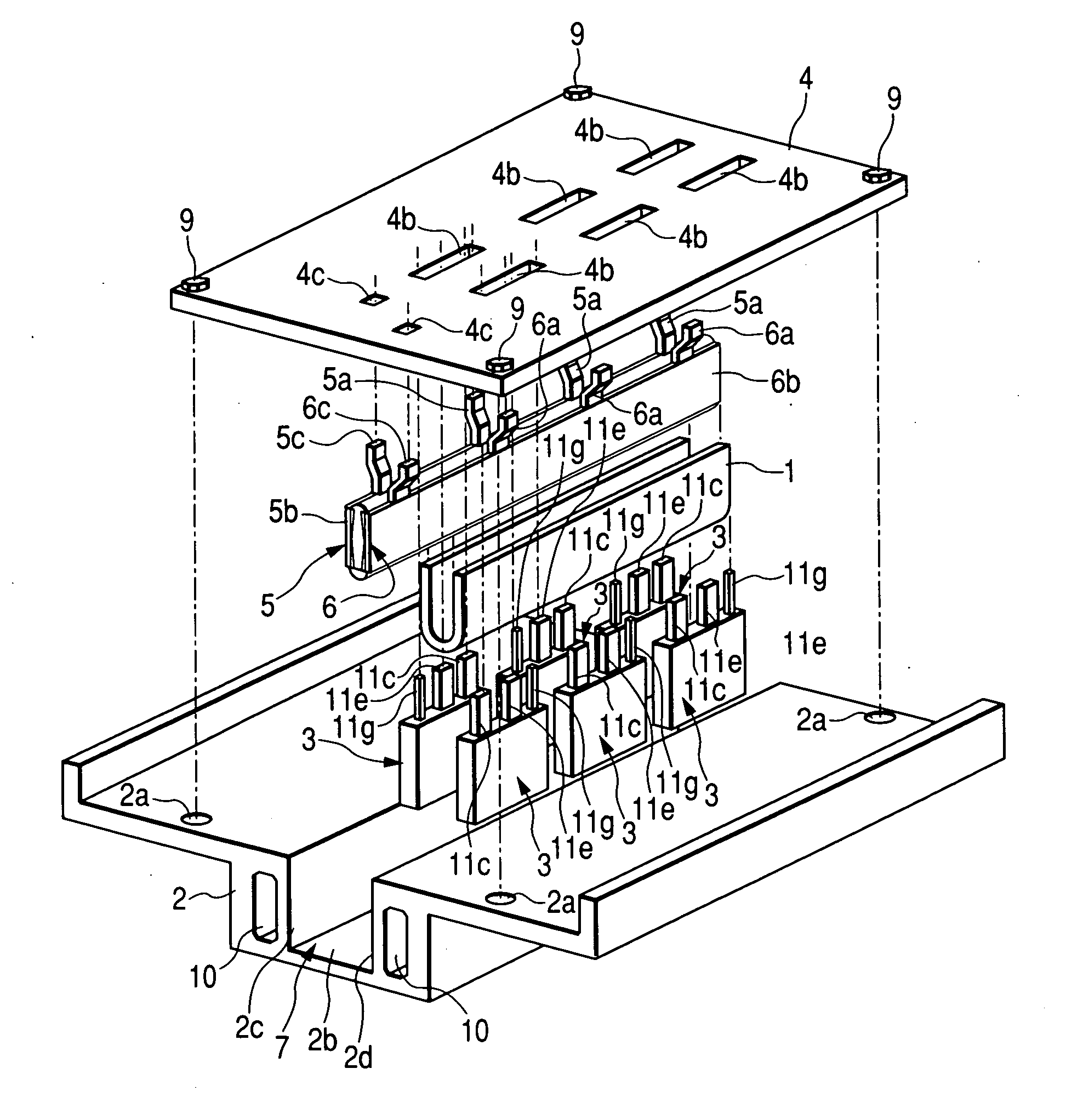
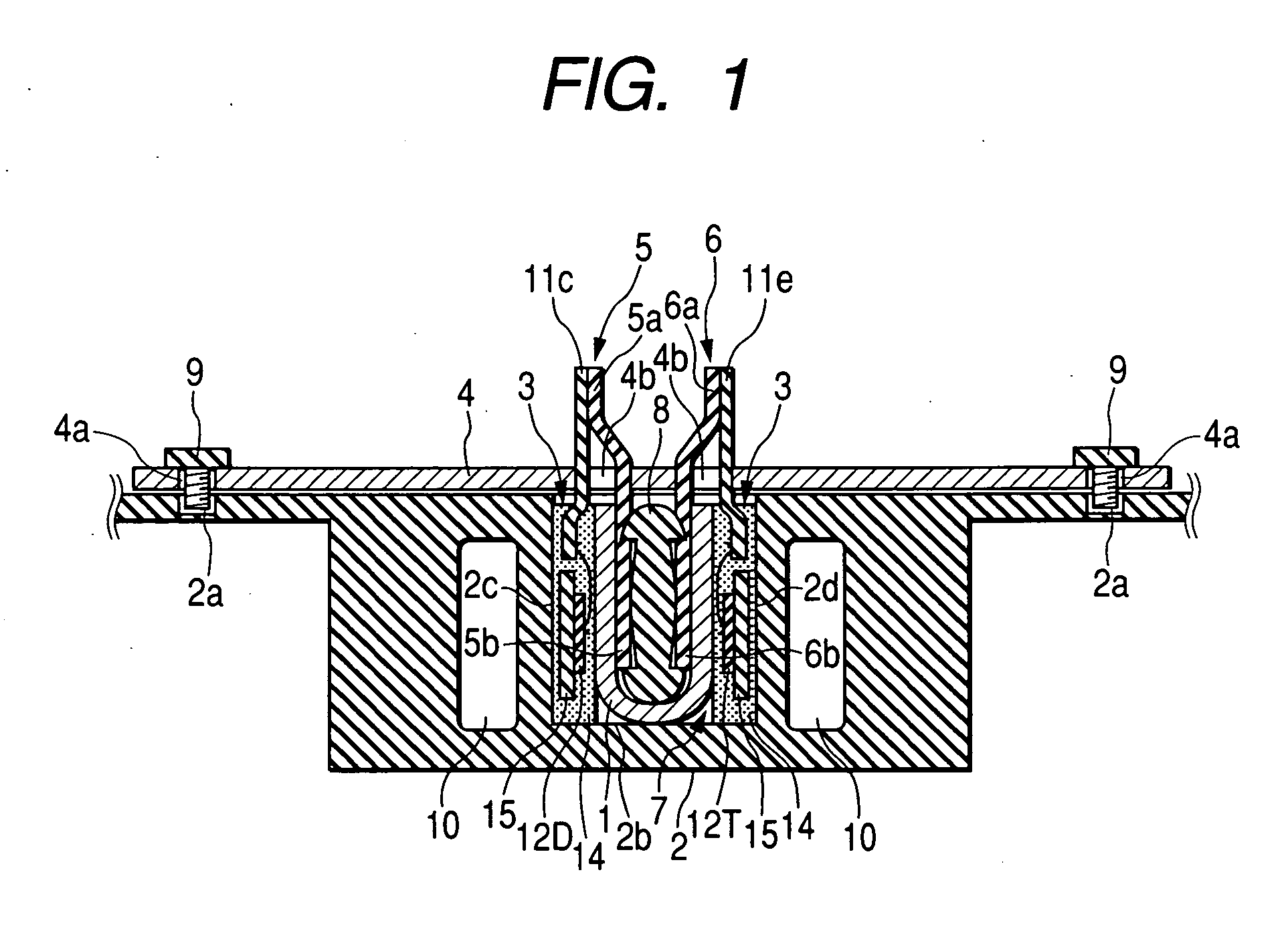
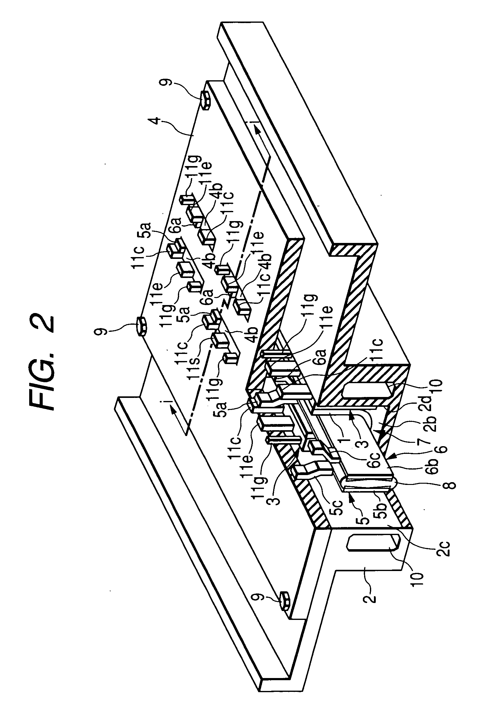
[0061] A first embodiment of the present invention will be described with reference to FIGS. 1 to 8.

[0062] First, a hybrid electric vehicle in this embodiment will be described by using FIG. 8.

[0063]FIG. 8 is a schematic diagram showing the structure of the power system of the hybrid electric vehicle in this embodiment.

[0064] The hybrid electric vehicle (referred to below as HEV) in this embodiment is one kind of electric vehicle and has two power systems: one of the power systems is an engine system that uses an engine ENG, which is an internal combustion engine, as an power source, the engine system being mainly used as the driving source of the HEV; the other is a vehicle-mounted electric system that uses a motor generator M / G as another power source. The vehicle-mounted electric system is mainly used as the driving source of the HEV and the electricity generating source of the HEV.

[0065] Front driving shaft FDSs are rotatably secured to the front of the body (not shown). A p...

embodiment 2

[0180] A second embodiment of the present invention will be described with reference to FIG. 9.

[0181]FIG. 9 shows the structure of an inverter INV in this embodiment.

[0182] This embodiment is an improvement of the first embodiment; protrusions 1a are formed on the surface, facing the semiconductor equipment 3, of each pressing part of the first fixing part 1. The protrusions 1a are formed integrally at a plurality of positions on the pressing parts of the first fixing tool 1 in the longer-side direction in correspondence with the array of semiconductor equipment 3 in such a way that the protrusions 1a touch the center on the surface, facing the first fixing tool 1, of the semiconductor equipment 3.

[0183] Other structures are the same as in the first embodiment; they are assigned the same reference numerals and their description is omitted.

[0184] According to this embodiment, protrusions 1a are formed on the surface, facing the semiconductor equipment 3, of each pressing part of ...

embodiment 3

[0185] A third embodiment of the present invention will be described with reference to FIG. 10.

[0186]FIG. 10 shows the structure of an inverter INV in this embodiment.

[0187] This embodiment is an improvement of the first embodiment; protrusions 24 are formed on the bottom wall surface 2b of the heat dissipating member 2. The protrusions 24 are fixing parts for fitting the semiconductor equipment 3 between the side wall surfaces 2c and 2d so that the semiconductor equipment 3 does not drop off or tip over when the semiconductor equipment 3 is inserted in the recess 7 of the heat dissipating member 2 and arrayed. The protrusions 24 are formed integrally at a plurality of positions on the bottom wall surface 2b of the heat dissipating member 2 in correspondence with the array of semiconductor equipment 3.

[0188] Other structures are the same as in the first embodiment; they are assigned the same reference numerals and their description is omitted.

[0189] According to this embodiment,...


PUM


Abstract

A power module constructs a pressurizing tool by laminating an elastic member as well as a DC positive-side wiring member and DC negative-side wiring member in which currents flow in opposite directions. The pressurizing tool presses a first fixing tool, and then the first fixing tool presses semiconductor equipment. The semiconductor equipment is fixed to a heat dissipating member with its heat dissipating surface brought into surface contact with side wall surfaces of the heat dissipating member. The power module can enhance heat dissipation between a heat dissipating member and semiconductor equipment, and enables the semiconductor equipment to be fixed to the heat dissipating member without adding other components to the power module.

Description

CLAIM OF PRIORITY [0001] The present application claims priority from Japanese application serial no. 2005-100486, filed on Mar. 31, 2005, the content of which is hereby incorporated by reference into this application. FIELD OF THE INVENTION [0002] The present invention relates to an electric circuit module as well as a power converter and vehicle-mounted electric system that use the module. BACKGROUND OF THE INVENTION [0003] Electric equipment that generates heat by itself due to electricity which flows in it, such as semiconductor equipment that controls electrical connections between electric circuits, is disposed and fixed on a heat dissipating member. This allows the heat from the semiconductor equipment to transmit to a coolant through the heat dissipating member, cooling the semiconductor equipment. Performance demanded for cooling electric equipment varies with environments of an electric appliance in which an electric circuit module including the electric equipment is mount...

Claims


Application Information

Patent Timeline
IPC IPC(8): H05K7/20B60L9/18H01L23/34H01L23/40H01L23/473H01L25/07H01L25/18H02M7/48
CPCB60L11/08B60L11/14B60L11/1868H01L23/3121H01L23/4093H01L23/473H01L23/4952H01L23/49562H01L23/49575H01L24/29H01L24/49H01L25/072H01L25/112H01L2224/0603H01L2224/32245H01L2224/48247H01L2224/48472H01L2224/49111H01L2224/49113H01L2224/73265H01L2924/01004H01L2924/01013H01L2924/01014H01L2924/01029H01L2924/01033H01L2924/01079H01L2924/01082H01L2924/01083H01L2924/014H01L2924/13055H01L2924/1815H01L2924/19041H01L2924/3011H01L2924/3025H02M7/003Y02T10/7005Y02T10/7066Y02T10/7077H01L24/48H01L2924/01005H01L2924/01006H01L2924/01023H01L2924/01024H01L2924/01068H01L2924/01074H05K7/1432H05K7/209H01L2924/13091H01L2224/48091H01L2924/30107H01L2924/1306H01L2924/1305Y02T10/70H01L2924/00H01L2924/00012H01L2924/00014H01L2924/181H01L2224/45124H01L2224/45147H01L24/45H01L24/73H01L2924/14H05K7/20927B60L50/13B60L50/16B60L58/20Y02T10/7072H05K7/14329H01L2224/45099
Inventor NAKATSU, KINYAIBORI, SATOSHIMIYAZAKI, HIDEKI
Owner HITACHI LTD
Why Eureka
Try Eureka