
Medical image processing apparatus

a technology of medical image and processing apparatus, applied in the field of medical image processing apparatus, can solve the problems of difficult to make data correspond to clinical diagnoses, image warp error may occur, and insufficient use of conventional techniques based on image warp, so as to achieve the effect of easy setting of roi

Inactive Publication Date: 2006-10-19
TOSHIBA MEDICAL SYST CORP
View PDF5 Cites 74 Cited by
  • Summary
  • Abstract
  • Description
  • Claims
  • Application Information

AI Technical Summary

Benefits of technology

[0012] The present invention has been made in consideration of the above situation, and has as its object to provide a medical image processing apparatus which can easily set an ROI for dividing an organ significantly in anatomical / functional terms while absorbing individual differences without performing warp processing for a diagnosis target image.

Problems solved by technology

If this mapping data is to be managed without any change, the amount of data to be managed becomes enormous, resulting in difficulty in making data correspond to clinical diagnoses.
In a conventional image division method based on ROI setting, however, the following problems arise.
First, a problem may be caused by an image warp error.
That is, an image warp error may occur due to a warp algorithm for a diagnosis target image, the quality of target data, or the difference (individual difference) between standardized data and a diagnosis target image.
This may cause artifacts.
For MRI and CT which originally have high spatial resolutions, higher accuracy is required than for SPECT and PET, and hence it is not always adequate to use a conventional technique based on image warp.
Second, an enormous processing cost may be required.
This nonlinear warp processing demands a high processing cost, and the cost may further increase depending on the number of data or the amount of data.
For example, in the case of MRI, this processing must be applied to all data of several parameter types even for one examination unit, and hence this problem is especially serious.
Third, the image division technique is not suitable for applications which do not require morphological warp of diagnosis target images.
That is, the conventional technique based on image warp cannot be applied to applications which do not want to warp the shapes of diagnosis target images, e.g., surgical operation and radiation therapy applications.
It is, however, technically difficult to perform such inverse warp because, for example, the spatial resolution has already been degraded.
Such an arrangement, however, is not practical.

Method used


Image

  • Medical image processing apparatus
  • Medical image processing apparatus
  • Medical image processing apparatus

Examples


first embodiment

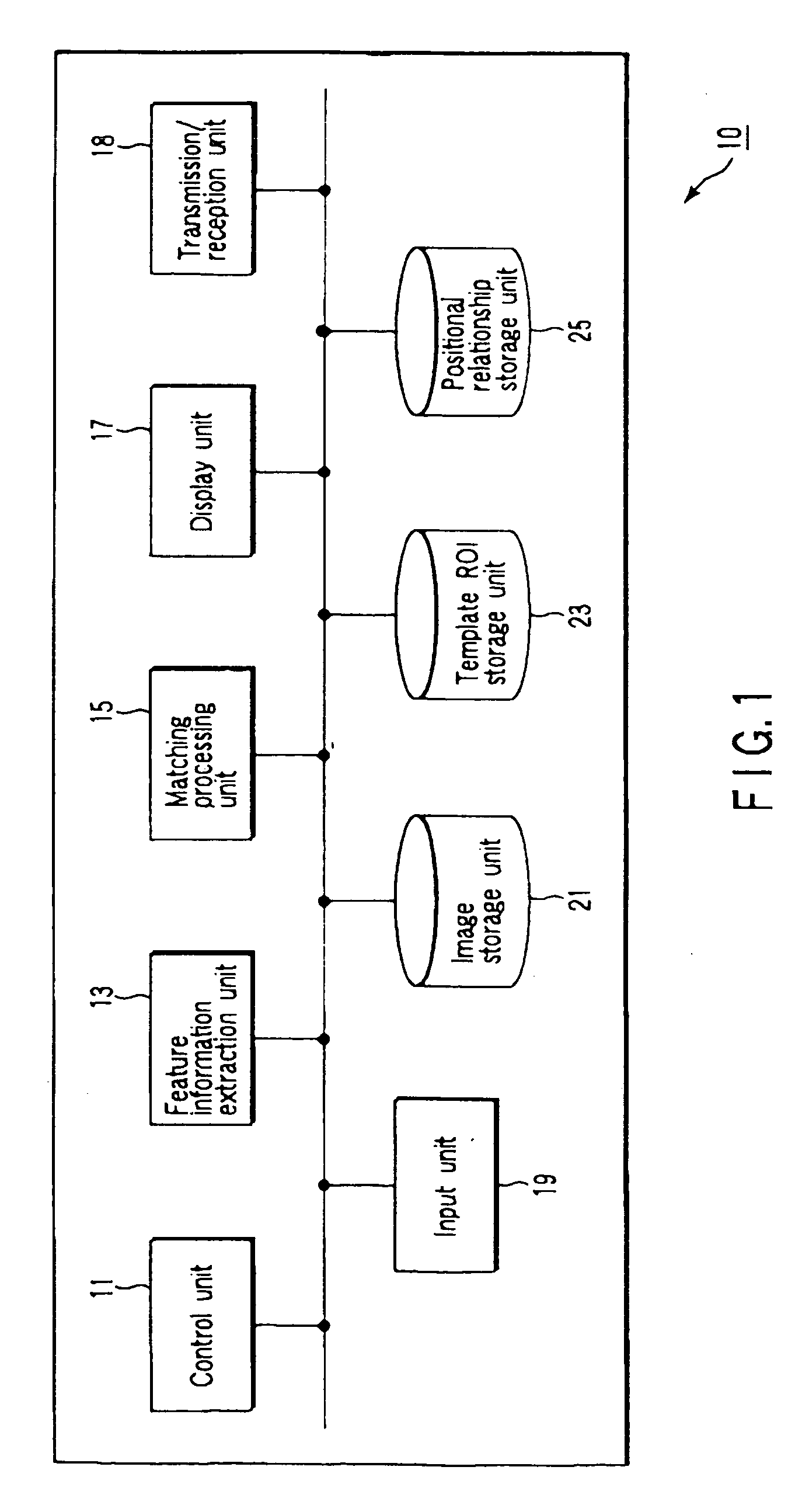
[0024]FIG. 1 is a block diagram showing the arrangement of a medical image processing apparatus 10 according to this embodiment. As shown in FIG. 1, the medical image processing apparatus 10 comprises a control unit 11, feature information extraction unit 13, matching processing unit 15, display unit 17, transmission / reception unit 18, input unit 19, image storage unit 21, template ROI storage unit 23, and positional relationship storage unit 25.

[0025] The control unit 11 performs overall control on the operation of the medical image processing apparatus 10. The control unit 11 performs control on an ROI warp matching function and the like (to be described later).

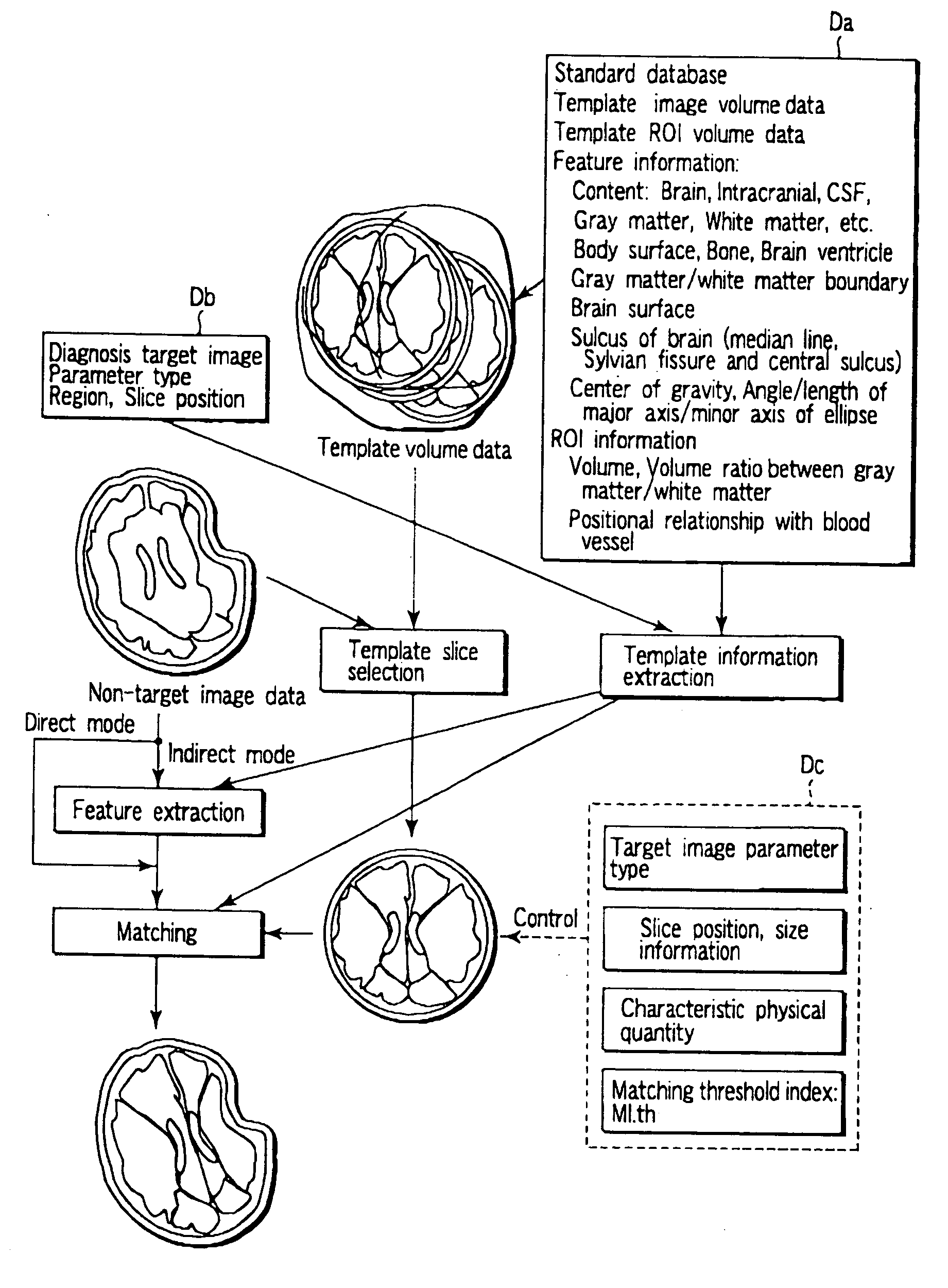
[0026] The feature information extraction unit 13 acquires feature information concerning various kinds of images such as a template ROI, standardized image, and diagnosis target image. In this case, for example, the following are diagnosis target images, standardized mage, and feature information concerning images.

[0027...

second embodiment

[0063] In the first embodiment, if diagnosis target image data is three-dimensional data which is small in slice thickness to some extent (5 mm or less) and covers the entire brain or organ, matching can be performed with high accuracy even in the slice axis direction when matching is performed up to three-dimensional matching. This makes it possible for the firs: embodiment to satisfactorily make diagnosis image data coincide with a template ROI.

[0064] If, however, diagnosis target image data is two-dimensional mage data limited to the slice axis direction, planning is made in advance to set a slice position at a desired position in imaging operation. However, diagnosis target image data and template ROI data may shift from each other in the slice axis direction. In this case, the “slice axis direction” is a direction orthogonal to a diagnosis target image and a corresponding template ROI as described in the first embodiment and parallel to the body axis direction. More specifical...


PUM


Abstract

A diagnosis target image is input, and a template ROI which is set on an image to divide the area on the image into predetermined areas in anatomical terms, physiological terms, or other scientific terms is read out from a storage unit. A matching processing unit warps the template ROI in correspondence with each diagnosis target image on the basis of the feature information of the diagnosis target image extracted by a feature information extraction unit. This warping is executed until an index indicating the degree of matching between the template ROI and the diagnosis image exceeds a predetermined threshold. The warped template ROI is displayed on a display unit upon being superimposed on the diagnosis image.

Description

CROSS-REFERENCE TO RELATED APPLICATIONS [0001] This application is based upon and claims the benefit of priority from prior Japanese Patent Application No. 2005-118770, filed Apr. 15, 2005, the entire contents of which are incorporated herein by reference. BACKGROUND OF THE INVENTION [0002] 1. Field of the Invention [0003] The present invention relates to a technique used for matching between an image acquired by medical imaging equipment and an ROI (Region Of interest) set on the image. [0004] 2. Description of the Related Art [0005] A medical image is generally obtained as mapping data having a value for each voxel obtained by dividing the image in the form of a lattice with a given size. If this mapping data is to be managed without any change, the amount of data to be managed becomes enormous, resulting in difficulty in making data correspond to clinical diagnoses. In general, therefore, some kind of information compression technique is used to store data as disease-specific dat...

Claims


Application Information

Patent Timeline
IPC IPC(8): G06K9/00
CPCG06T7/0024G06T2207/30016G06T2207/10072G06T7/30
Inventor KIMURA, TOKUNORI
Owner TOSHIBA MEDICAL SYST CORP
Features
  • Generate Ideas
  • Intellectual Property
  • Life Sciences
  • Materials
  • Tech Scout
  • Unparalleled Data Quality
  • Higher Quality Content
  • 60% Fewer Hallucinations
Learn More