Image data decoding apparatus and method

a decoding apparatus and image data technology, applied in the field of image data decoding apparatus and method for decoding compressed image data, can solve the problem of inability to increase the processing speed of variable length decoding device, and achieve the effect of increasing the quantization coefficient, increasing the buffer capacity, and increasing the decoding process speed

Inactive Publication Date: 2006-10-19
RENESAS ELECTRONICS CORP
View PDF4 Cites 21 Cited by
  • Summary
  • Abstract
  • Description
  • Claims
  • Application Information

AI Technical Summary

Benefits of technology

[0013] That is, according to the present invention, it is possible to provide a image data decoding apparatus and method capable of decoding more quantization coefficients from compressed image data without increasing a buffer capacity, and increasing a decoding process speed and applicable to a general-purposed structure.

Problems solved by technology

That is, there is a limitation on the quantization coefficient storable in the quantization coefficient FIFO 105, making it impossible to increase a processing speed of the variable length decoder.

Method used


Image

  • Image data decoding apparatus and method
  • Image data decoding apparatus and method
  • Image data decoding apparatus and method

Examples


first embodiment

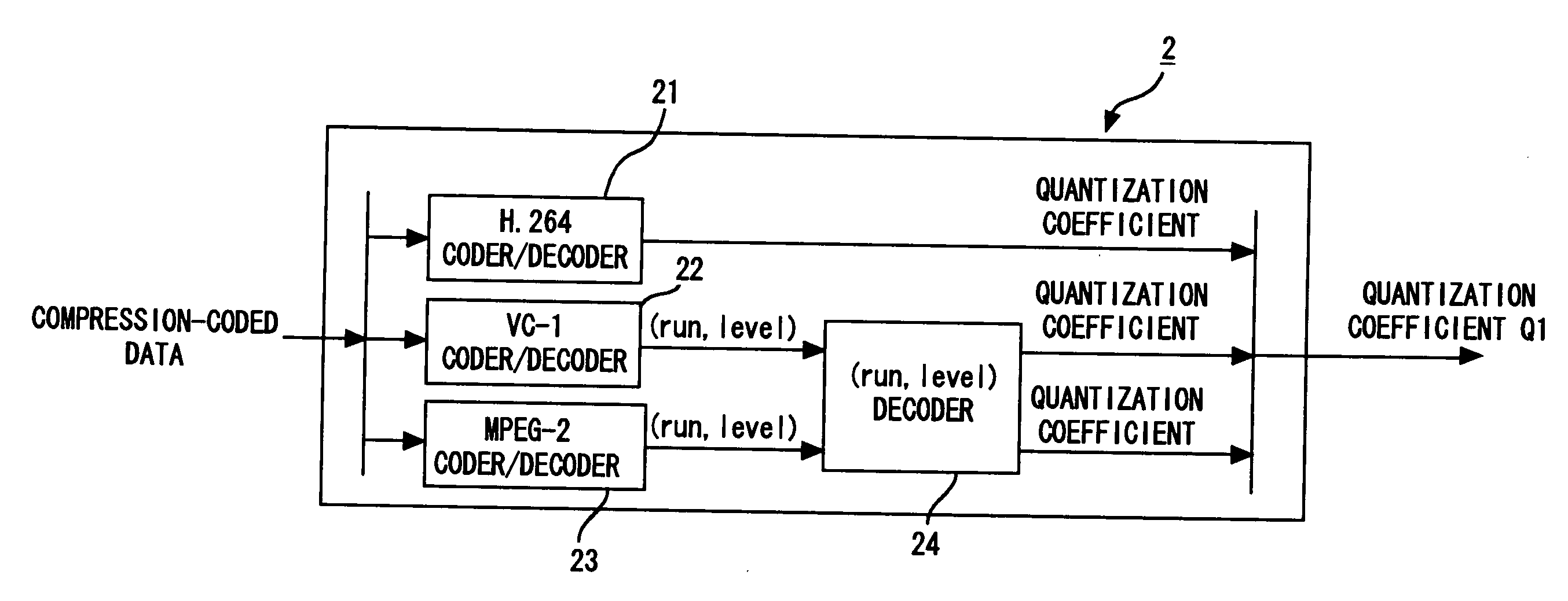
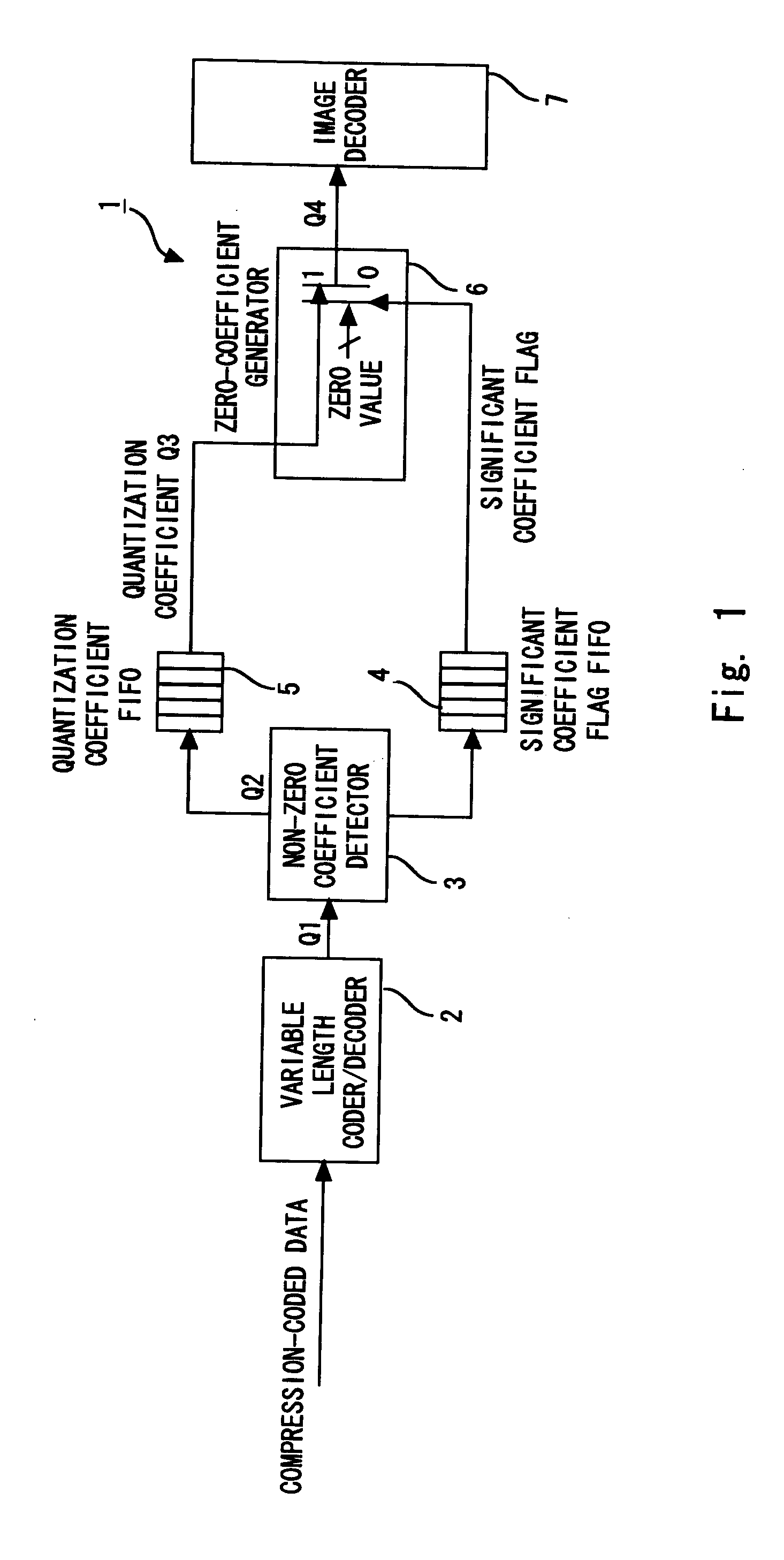
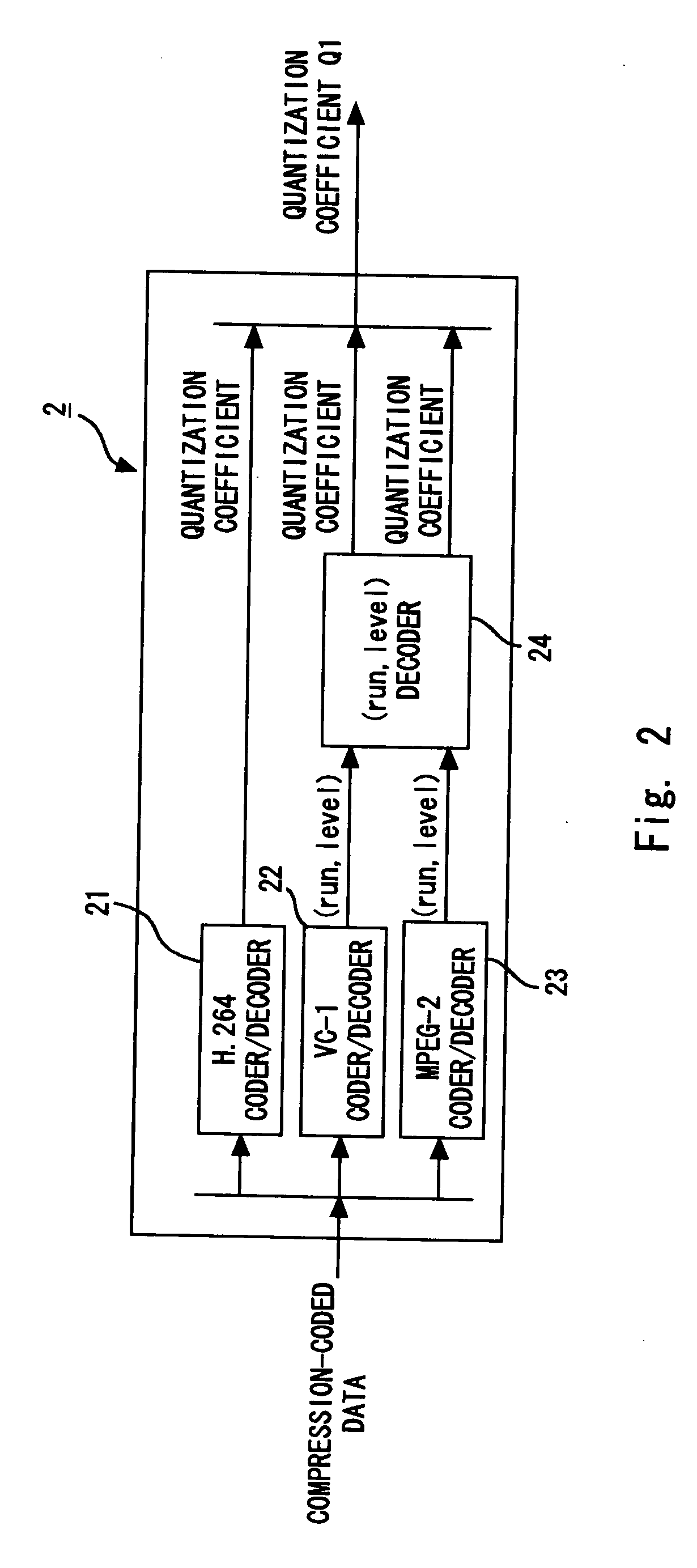
[0031] Hereinafter, embodiments of the present invention are described in detail with reference to the accompanying drawings. FIG. 1 is a block diagram showing an image data decoding apparatus according to a first embodiment of the invention. As shown in FIG. 1, the image data decoding apparatus 1 of this embodiment includes a variable length coder / decoder 2 that receives compression-coded data (compressed bit stream), and outputs a quantization coefficient Q1, and a non-zero coefficient detector 3 that determines whether the quantization coefficient Q1 is a non-zero coefficient or zero coefficient.

[0032] The compression-coded data is generated as follows if conforming to MPEG-2, for example. That is, an image signal of a moving picture to be coded is divided into blocks including plural pixels (for example, 8×8 pixels), and then, an image signal or a prediction error signal representing an error between an image signal and a prediction signal is subjected to discrete cosine transf...

second embodiment

[0064] Next, a second embodiment of the present invention is described. In the description of the above first embodiment, the examination unit is a fixed unit but may be variable. A second embodiment of the invention aims at setting the examination unit variable to further reduce a capacity of a memory for storing the quantization coefficients or improve a buffering efficiency of the quantization coefficients.

[0065] A feature of a general image is that most of the components concentrate around the upper left portion of the block in inverted data. In the compressed image, an occurrence rate of the non-zero coefficients becomes lower from the upper left portion of the block towards the lower right portion based on the above feature. Based on this feature, the examination unit on the upper left side is set to 1, and a value may be increased toward the lower right portion to nonuniformly set values of the examination units in the block.

[0066] This embodiment describes an example where...

third embodiment

[0078] Next, an image data decoding apparatus according to a third embodiment of the present invention is described. In this embodiment, similar to the second embodiment, the examination unit is variably set. However, instead of setting the examination unit with reference to a table irrespective of input image data, the examination units are adaptively switched in accordance with the image data depending on the number of non-zero coefficients.

[0079]FIG. 11 is a block diagram showing a non-zero coefficient detector 43 of the image data decoding apparatus according to this embodiment. Incidentally, the same components as those of the non-zero coefficient detector 3 of FIG. 3 are denoted by like reference numerals. A detailed description thereof is omitted. Further, the other components of the image data decoding apparatus may be structured similarly to the image data decoding apparatus according to the first embodiment of FIG. 1.

[0080] As shown in FIG. 11, the non-zero coefficient d...


PUM


Abstract

An image data decoding apparatus according to an embodiment of the invention includes: a variable length coder / decoder for decoding compressed image data to output a quantization coefficient; a non-zero coefficient detector for examining whether or not the quantization coefficient includes a non-zero coefficient for each examination unit; a quantization coefficient FIFO for storing, if the examination unit includes one or more non-zero coefficients, the quantization coefficient of the examination unit as a significant coefficient; a significant coefficient flag FIFO for storing a significant coefficient flag that indicates whether or not the examination unit is a significant coefficient, and a zero coefficient generator for reconstructing the quantization coefficient based on the significant coefficient flag and significant coefficient.

Description

BACKGROUND OF THE INVENTION [0001] 1. Field of the Invention [0002] The present invention relates to an image data decoding apparatus and method for decoding compressed image data. In particular, the invention relates to an image data decoding apparatus and method that improve a processing speed at the time of decoding highly compressed image data based on such as the MPEG (Moving Picture Expert Group)-2, H.264, or VC-1 (WMV9). [0003] 2. Description of Related Art [0004] New codecs such as H.264 and VC-1 intended for next-generation DVDs (digital versatile disks) or DTVs (digital televisions) are more advantageous than MPEG-2 in terms of the following points. 1) An efficiency for intra prediction (motion prediction) is improved to reduce data to be compressed (non-zero coefficient). 2) A precision of variable length coding / decoding processing is improved. 3) Encoded data is further compressed based on code prediction processing or arithmetic coding to realize high-level compressi...

Claims


Application Information

Patent Timeline
Patent Type & Authority Applications(United States)
IPC IPC(8): G06K9/36H04N19/00H04N19/423H04N19/426H04N19/44H04N19/503H04N19/61H04N19/625H04N19/91H04N19/93
CPCH04N19/91H04N19/132H04N19/18H04N19/93H04N19/42H04N19/426H04N19/44
Inventor MATSUBARA, KATSUSHIGE
Owner RENESAS ELECTRONICS CORP
Why Eureka
Try Eureka