Buoyancy pump power system

a power system and pump technology, applied in the direction of electric generator control, positive displacement liquid engine, fluid coupling, etc., can solve the problems of limiting the placement of the system, system undesirable, and each system is replete with problems

Inactive Publication Date: 2006-10-19
INDEPENDENT NATURAL RESOURCES
View PDF38 Cites 43 Cited by
  • Summary
  • Abstract
  • Description
  • Claims
  • Application Information

AI Technical Summary

Problems solved by technology

Each of these systems is replete with problems.
These systems involve numerous mechanical parts which require constant maintenance and replacement, and therefore make the system undesirable.
Other systems are limited to construction only at sea shore or in shallow water, which limit placement of the systems and therefore make the systems undesirable.
Finally, other systems fail to use the full energy provided by the wave phenomena, and therefore waste energy through collection, resulting in an inefficient system.
The decline in readily available traditional fuel sources has lead to an increase in the costs of energy, which is felt globally.
Such projects can take twenty or more years to finish.

Method used


Image

  • Buoyancy pump power system
  • Buoyancy pump power system
  • Buoyancy pump power system

Examples


example a

Low Wave Size

1. Wave Horsepower

[0114] Referring more specifically to FIGS. 4A-4D, wave horsepower (Wave HP) is determined for a wave (W) traveling over a distance of one-half the wave length (½ WL) as follows:

Wave HP=[(WV)(D) / (HP)](WS)

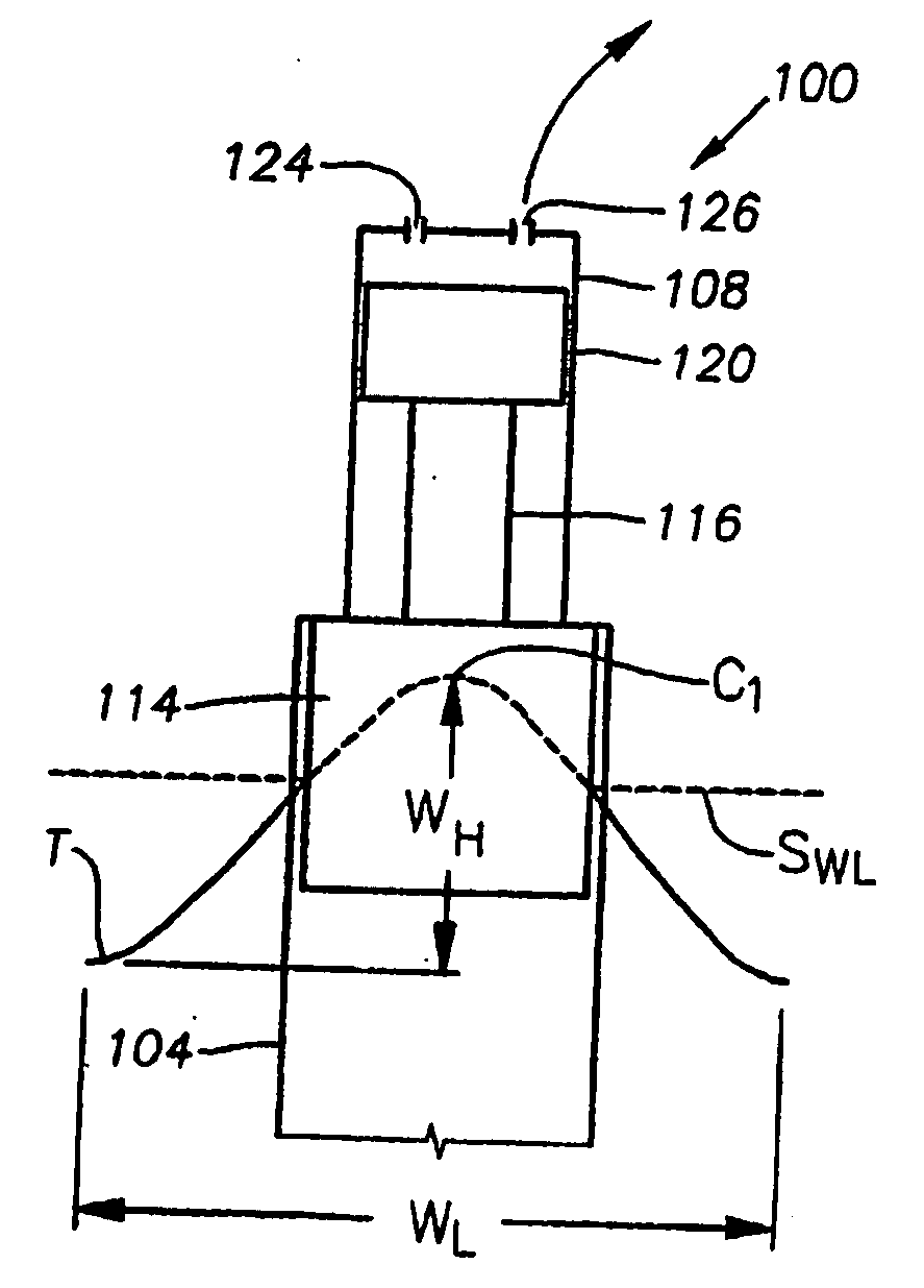
where [0115] WV(Wave Volume)=(WW)(WD)(WH)(gallons water / ft3) [0116] WW=Wave Width (½ WL)=17.5 feet [0117] WD=Wave Depth=17.5 feet [0118] WH=Wave Height=5 feet

and [0119] D=density of water (8.33 lbs / gal)

and [0120] HP=horse power unit (550)

and [0121] WS=Wave Speed (½ WL / WT)

and [0122] WT=Wave time to travel ½ WL (7.953 sec).

[0123] For example, the wave depth (WD) is assumed to be equal to the wave width (WW) so that the profile of the wave (W) will completely cover the buoyancy block 114′ which is cylindrical in shape. For the numbers indicated above which are exemplary, the calculations are as follows:

Wave HP=[(11,453 gal)(8.33 lbs / gal) / (550)](2.2 ft / sec)=382

where [0124] WV=(1,531 ft3)(7.481 gal / ft3)=11,453 gal; and [0125] WS=(17.5 feet...

example b

Average Wave Size

[0182] The above-exemplary calculations were made with an exemplary buoyancy block 114′ having a fixed diameter (d1) depending on the geometry of the buoyancy block 114′ and height (h1+h2). It is to be appreciated that the wave height (WH) varies for different locations and for different times during the year at each location. Thus, it is desirable to reconfigure or adjust this buoyancy block based on the varying wave characteristics as described above. To ensure high efficiencies, the height and / or diameter of the buoyancy block 114′ can be adjusted. For example, the buoyancy block 114′ can be designed or adjusted to increase the height of its base 104′a (h1) and related diameter to accommodate waves having a greater wave height (WH) as will be described below.

[0183] Assuming that the wave height (WH) increases from 5.0 ft. to 9.016 ft. (an average sized wave), the height of the buoyancy block base (h1) is increased by 1.5 ft. (see FIG. 4D), i.e., the “warp” of t...


PUM


Abstract

A system for generating electricity includes a pump operable to convert wave motion from a body of water into mechanical energy. The pump includes an input port through which an operating fluid can enter the pump and an output port through which the operating fluid can exit the pump. A first outlet line and a second outlet line are fluidly coupled to the output port of the pump. A first reservoir is fluidly connected to the first outlet line, and a second reservoir is fluidly connected to the second outlet line, both reservoirs being selectively capable of receiving operating fluid driven through the output port.

Description

CROSS-REFERENCE TO RELATED APPLICATIONS [0001] This application claims the benefit of and priority to U.S. Provisional Application No. 60 / 636,492, filed Dec. 16, 2004, and U.S. Provisional Application No. 60 / 653,618, filed Feb. 16, 2005, which are hereby incorporated by reference.BACKGROUND OF THE INVENTION [0002] 1. Field of the Invention [0003] The present invention relates, in general, to a pumping device, and more particular but not by way of limitation, to a buoyancy pumping device in a buoyancy pump power system that utilizes a moving volume of water to move gas, liquid and combinations thereof from a first location to a second location. [0004] 2. Description of Related Art [0005] There have been many attempts to harness what is commonly referred as to wave phenomena and to translate energy observed in wave phenomena into usable, reliable energy sources. Wave phenomena involves the transmission of energy and momentum by means by vibratory impulses through various states of mat...

Claims


Application Information

Patent Timeline
Patent Type & Authority Applications(United States)
IPC IPC(8): E02B9/08
CPCE02B9/08F03B13/187F03B13/1875F04B17/00Y02E10/38F05B2240/40F05B2240/93F05B2270/708F05B2210/16Y02E10/30F03B13/12E02B3/00
Inventor WELCH, KENNETH W. JR.ROTHI, CURTIS J.ROTHI, HAROLD L.
Owner INDEPENDENT NATURAL RESOURCES
Why Eureka
Try Eureka