
Printed sheet for flooring material and flooring material

Inactive Publication Date: 2006-10-19
DAI NIPPON PRINTING CO LTD
View PDF0 Cites 10 Cited by
  • Summary
  • Abstract
  • Description
  • Claims
  • Application Information

AI Technical Summary

Benefits of technology

[0008] In view of the above circumstances, an object of the present invention is to provide a flooring material having improved stability and strength and to provide a printed sheet for flooring material, to be used in such a flooring material.
[0018] According to the flooring material of the above present invention, there can be provided a flooring material in which each of the layers is hardly delaminated and which thereby acquires stability and is also improved in the strength thereof.

Problems solved by technology

Such a flooring material is involved in a problem that delamination tests of each of the layers, carried out before and after weatherability test, reveal that each layer tends to be delaminated, more specifically, the interface between the backer layer (1) and the printed sheet (2) and the interface between the printed sheet (2) and the top sheet (3) frequently undergo delamination, making the stability of the flooring material poor as the case may be.

Method used


Image

  • Printed sheet for flooring material and flooring material
  • Printed sheet for flooring material and flooring material

Examples


example 1

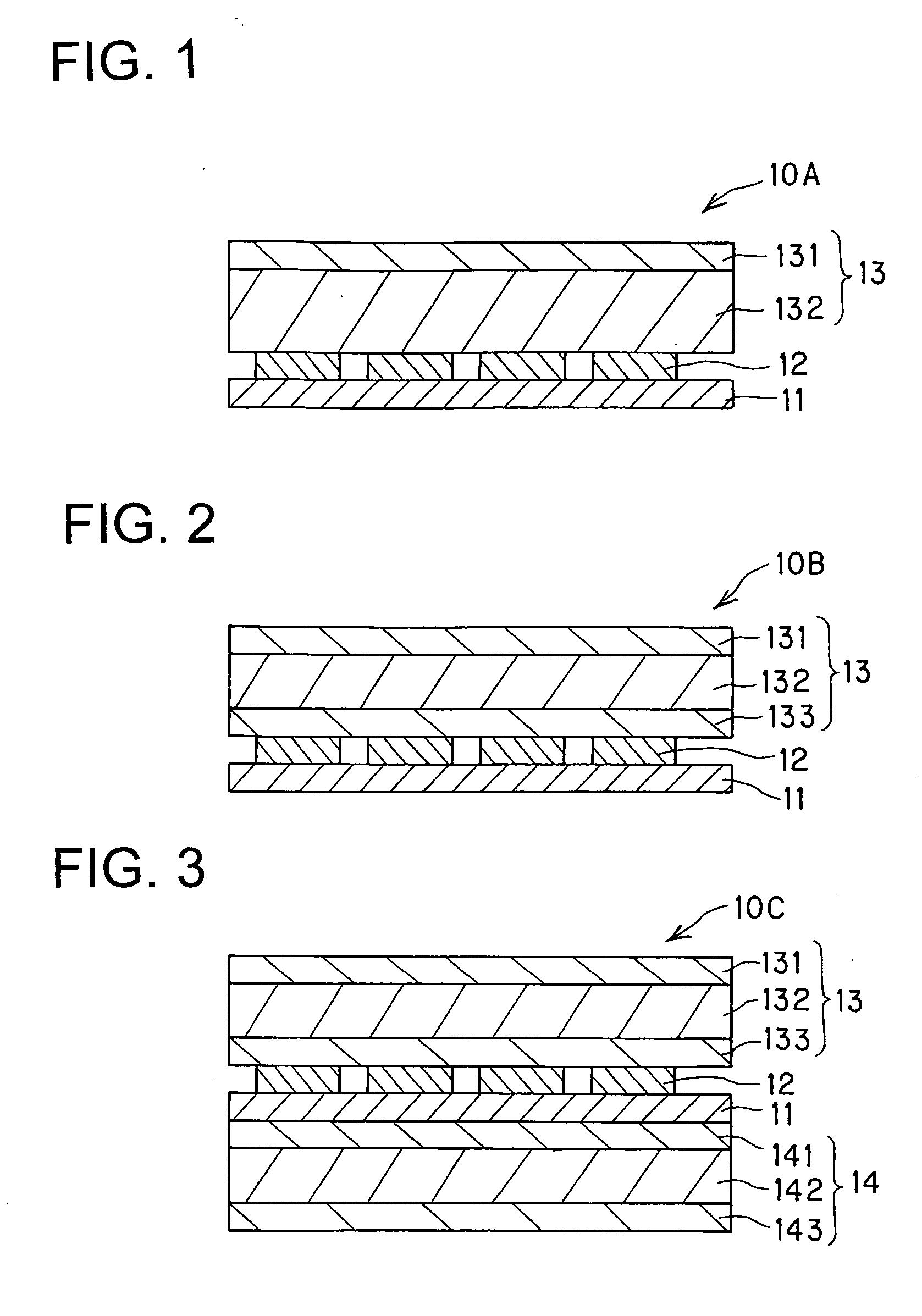
[0067] As the first composite material layer, an 80 μm thick sheet was fabricated by co-extrusion molding of a 20 μm thick EMAA resin layer made of the EMAA resin having the fraction of MA of 5% and a 60 μm thick first polyethylene resin layer made of LLDPE(1). In this case, the first polyethylene resin layer was formed by co-extruding a 50 μm thick layer contacting with the EMAA resin and another 10 μm thick layer non-contacting with the EMAA resin.

[0068] The surface on the first polyethylene layer side of the first composite material layer was subjected to corona treatment, and on the thus treated surface, a printed layer was partially formed by gravure printing using a two-pack curing type urethane ink composed of acrylpolyol and 1,6-hexamethylene diisocyanate.

[0069] Then, on the first composite material layer and the printed layer, a urethane type resin layer was formed as a 15 μm thick layer by laminating a urethane type resin by gravure reversing process. Thus, a printed she...

example 2

[0073] A flooring material of Example 2 was obtained by fabricating a printed sheet for flooring material and a flooring material in same manner as in Example 1, except that the layer thickness of the EMMA resin layer was 19 μm, and the first polyethylene resin layer was formed as a 30.5 μm thick single layer made of another LLDPE(2) and a 30.5 μm thick layer made of HDPE was formed as a second polyethylene resin layer on a side of the printed layer of the first polyethylene resin layer.

example 3

[0074] A flooring material of Example 3 was obtained by fabricating a printed sheet for flooring material and a flooring material in same manner as in Example 2, except that the layer thickness of the EMMA resin layer was 20 μm, and the first polyethylene resin layer was formed as a 40 μm thick single layer made of the above described LLDPE(2) and a second polyethylene resin layer was formed as a 20 μm thick layer made of a resin prepared by blending EMMA and the LLDPE (2) in a ratio of 3:7.


PUM


Abstract

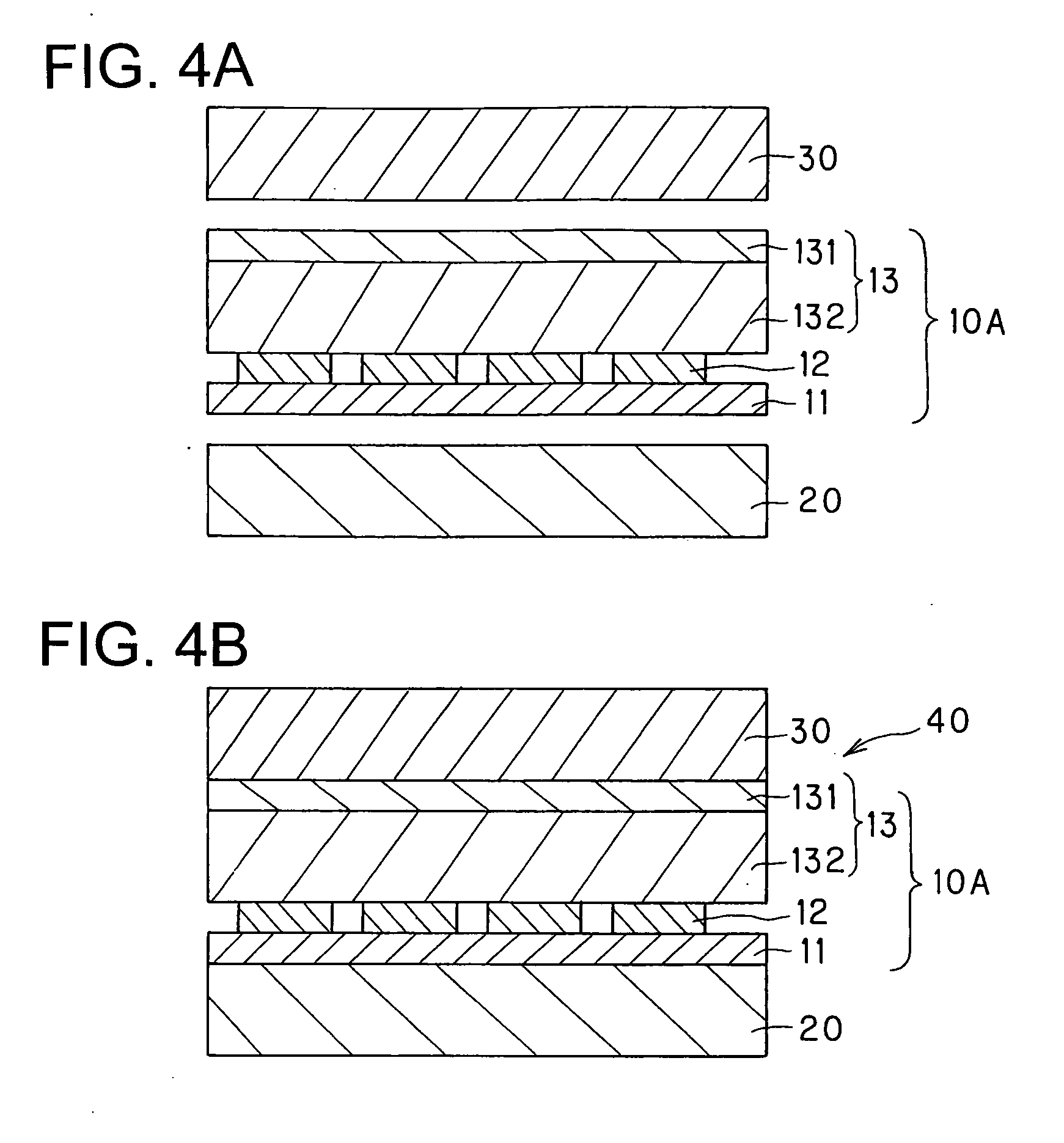
A printed sheet for flooring material to be disposed between a backer layer and a top sheet in a flooring material, wherein: the printed sheet for flooring material comprises at least a urethane type resin layer, a printed layer, and a first composite material layer; the printed sheet for flooring material comprises the urethane type resin layer and the first composite material layer in this order from a side of the backer layer in the printed sheet; and the first composite material layer comprises at least an EMAA resin layer and a first polyethylene resin layer in this order from a side of the top sheet in the printed sheet.

Description

BACKGROUND OF THE INVENTION [0001] 1. Field of the Invention [0002] The present invention relates to a flooring material and a printed sheet for flooring material to be included in the flooring material. More particularly, the present invention relates to a printed sheet for flooring material which has improved stability by preventing delamination, and the like. [0003] 2. Related Art [0004] As a flooring material to be used as a building material, there is known a flooring material in which a backer layer (1), a printed sheet (2) and a topsheet (an ionomer resin layer) (3) are laminated. Such a flooring material is usually fabricated by interposing the printed sheet (2) between the backer layer (1) and the top sheet (3) and by subjecting the laminate thus obtained to heat lamination. The printed sheet (2) as referred to herein is formed by sequentially laminating, from a side of the backer layer of the printed sheet (2), a primer layer, a printed layer and a layer of an ionomer resi...

Claims


Application Information

Patent Timeline
IPC IPC(8): B44C1/17
CPCB32B27/08Y10T428/24802E04F15/16B32B3/10B32B3/18B32B27/308B32B27/32B32B27/40B32B2323/04B32B2333/00B32B2471/00
Inventor TAJIMA, ISAOORIKASA, TOSHIYUKIKOORIYAMA, KAYOKO
Owner DAI NIPPON PRINTING CO LTD
Learn More