[0007] The present invention includes a
system and method for managing inertial torque reaction by rotating inertial powertrain or
drivetrain components a direction opposite to the rotation of engine / motor inertial components, to reduce or eliminate torque reaction on stationary powertrain components.
[0009] In a transversely mounted
internal combustion engine and
transaxle, as generally used in, but not limited to,
front wheel drive (FWD) vehicles, for example, the
crankshaft and the
torque converter may be connected using toothed wheels enabling the
torque converter and
crankshaft to rotate in opposite directions. A separate or integrated device may be used to reduce or eliminate backlash and associated
noise, such as a scissors gear, for example. The opposing direction of rotation of the crankshaft and torque converter reduces or eliminates the inertial torque reaction on the stationary powertrain structure to reduce or eliminate unwanted vibration and noise.
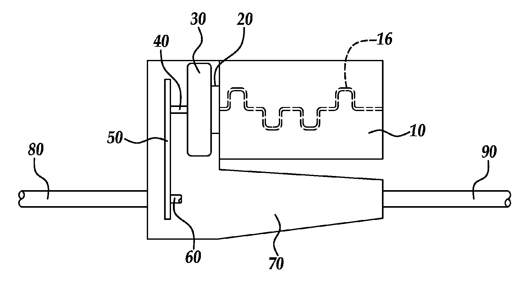
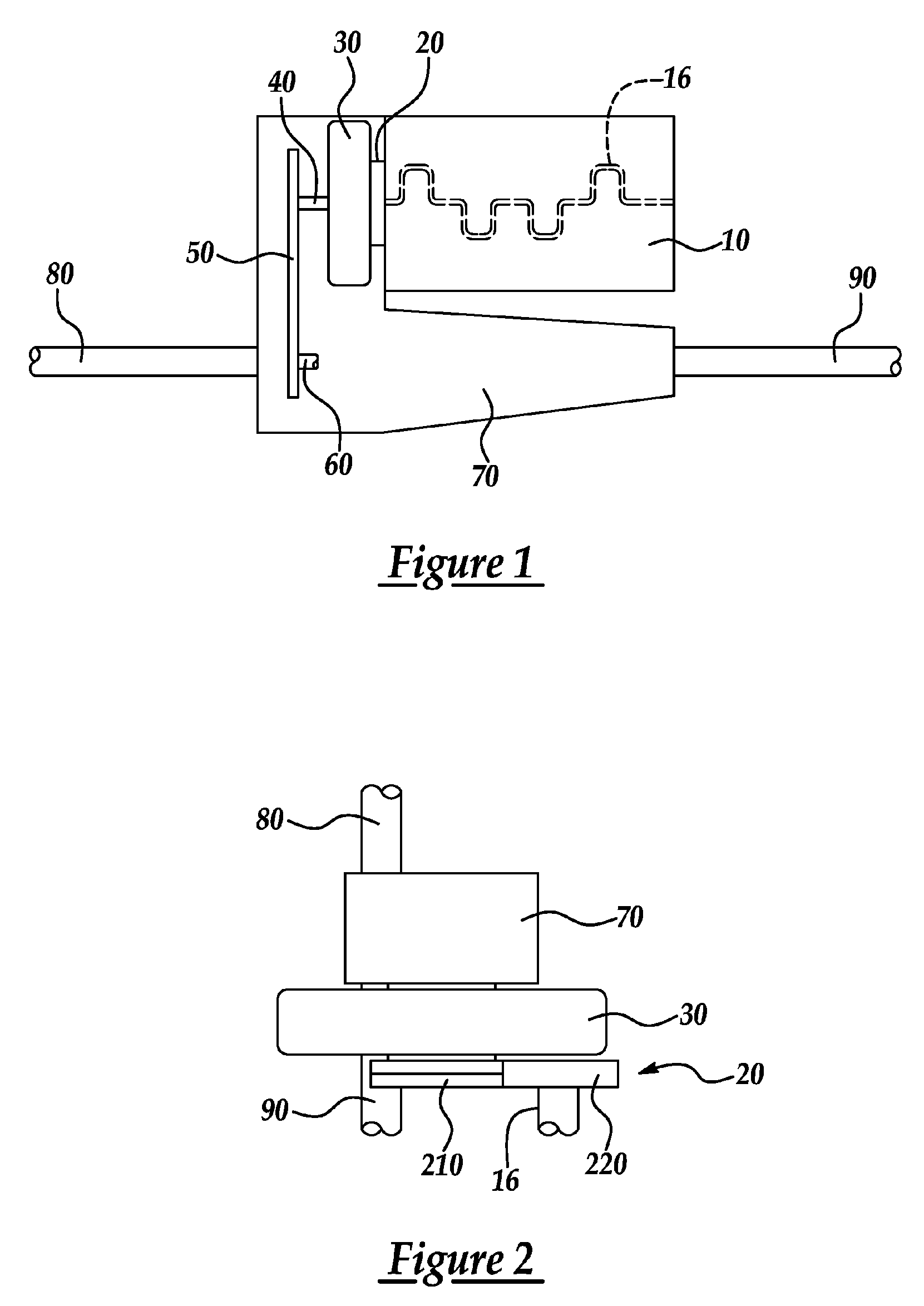
[0010] A longitudinally mounted engine and transmission application, as generally used in, but not limited to, rear
wheel drive (RWD) vehicles, for example, may incorporate a simple planetary gear set to connect the crankshaft to the torque converter. Such a planetary gear set typically includes a sun gear, a ring gear, and a carrier with a plurality of pinions that are constantly in mesh with the sun and ring gears. In such an arrangement, for example, the carrier may be rendered stationary by using a plurality of fasteners to connect it with the engine /
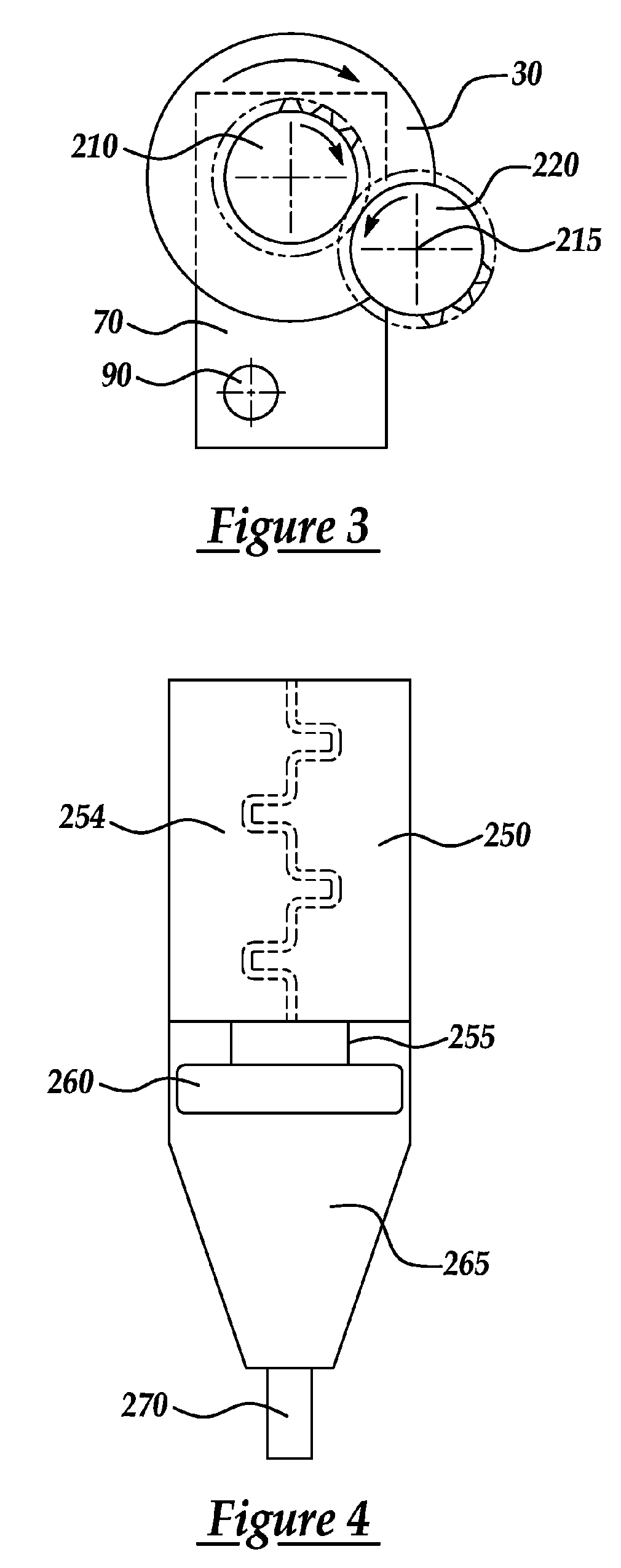
motor block. The sun gear of the planetary gear set may be connected to the crankshaft using any of a variety of methods including using conventional fasteners or alternatively splines with at least one
retaining ring. Likewise, the ring gear or the annulus of the planetary gear set may be connected to the engine / motor flex plate using a plurality of fasteners. Such an arrangement allows the ring gear to rotate in a direction opposite to that of the sun gear when the carrier is non-rotating. Thus, at least one
drivetrain component, such as the torque converter, will rotate in a direction opposite to that of the crankshaft and create corresponding rotational inertia to reduce or eliminate the inertial torque reaction otherwise associated with a change in
angular acceleration / deceleration of rotating components of the engine on the stationary powertrain structure reducing or eliminating associated noise and vibration.
[0011] The present invention provides a number of advantages. For example, the present invention provides systems and methods for managing inertial torque reaction by providing a counter-rotating inertia generated by conventional powertrain components to reduce or eliminate the torque reaction on the powertrain structure and improve performance with respect to noise, vibration, and
harshness (NVH). Reversing rotation of conventional powertrain components obviates the need for additional components or
mass to generate balancing inertia. This reduces any adverse
impact on powertrain weight, responsiveness, and overall performance relative to conventional solutions that add components solely for balancing or canceling torque reactions associated with rotating inertia.
[0012] The present invention may allow
variable displacement engines to idle and drive at low engine speeds with fewer than all of the cylinders firing without unacceptable NVH. Also, the reduced or limited inertial torque reaction on the stationary powertrain structure should reduce noise, vibration, and
harshness (NVH) with the uneven firing intervals that occur when an 8-
cylinder engine operates in a reduced or
variable displacement mode with 3, 5, 6, or 7 firing cylinders, for example.

