
Electrosurgical tool

Active Publication Date: 2006-10-19
STRYKER CORP
View PDF30 Cites 120 Cited by
  • Summary
  • Abstract
  • Description
  • Claims
  • Application Information

AI Technical Summary

Benefits of technology

[0009] Further, the tool according to the invention helps to resolve the spatial limitations of existing tools by eliminating the need for both a suction tube and electrode wiring to pass through the outer tool shaft and the insulator cap disposed at the distal end thereof, since a single tube serves both as a suction tube and as a conduit for delivering electrical energy to the electrode at the tip of the tool, and since only one passage must be defined through the insulator cap. As such, the internal diameter of the outer shaft can be significantly reduced, since no additional space is needed therein for electrode wiring. In addition, the diameter of the distal end of the tool can be reduced essentially to the size of the active electrode, plus the minimal ceramic thickness necessary for insulation purposes.

Problems solved by technology

The delivery of a high-frequency current between the active and return electrodes effectively modifies tissue, and it is common for bubbles to form on the surface of the tool or probe tip which can interfere with the surgeon's view of the surgical site.
This is particularly a problem when the electrosurgical tool is employed in an endoscopic surgical procedure, wherein the electrosurgical tool is inserted into the surgical site through a small opening or portal formed in the patient's body.
Thus, these bubbles are generated in the relatively small confines of the surgical site and cause significant problems for the surgeon in viewing the surgical site.
Further, these bubbles are electrically and thermally insulating, and can inhibit the flow of new saline solution for rewetting the electrode.
Consequently, the bubbles can cause undesirable reduction of current flow through the targeted tissue.
While the above tool works reasonably well for its intended purpose, the requirement for the outer shaft to house both a suction tube and wiring for delivering current to the active electrode presents difficulties in assembly of the tool.
Further, this arrangement results in limited available space within the outer shaft, which places a limit on the diameter of a suction tube.
In addition, the cap which insulates the active electrode from the return electrode is required to have multiple holes for accommodating the active electrode and suction tube, which makes it difficult to minimize the overall diameter of the insulator cap and thus the overall diameter of the tool tip.
However, a disadvantage of the above devices is that they utilize the suction tube directly for delivery of electrical energy to the targeted tissue.
However, the rate of fluid flow over this ring and into the suction passage of the suction tube can cause convective cooling at the periphery of the electrode, which can result in the inability to rapidly ablate tissue.

Method used


Image

  • Electrosurgical tool
  • Electrosurgical tool
  • Electrosurgical tool

Examples


Embodiment Construction

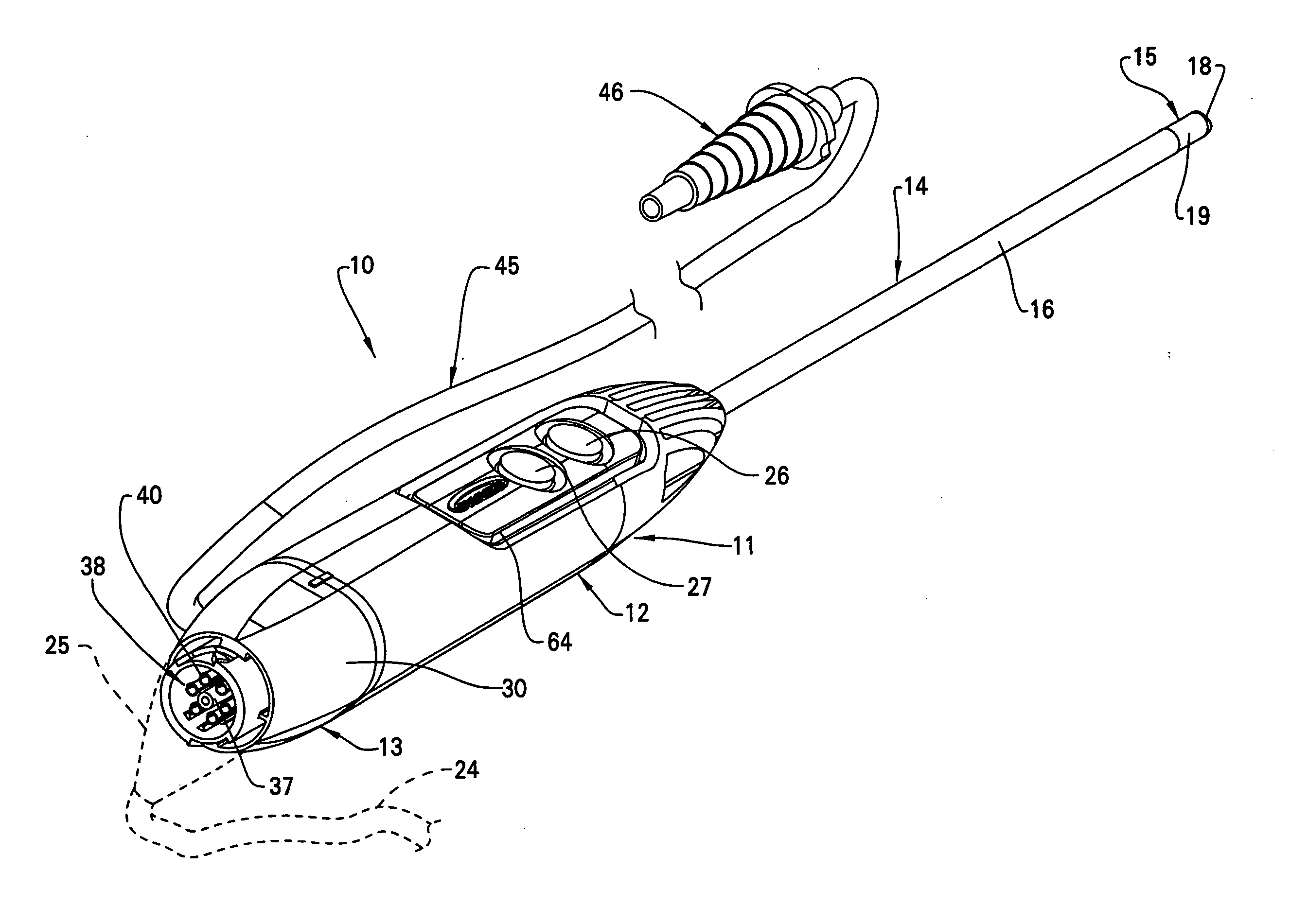
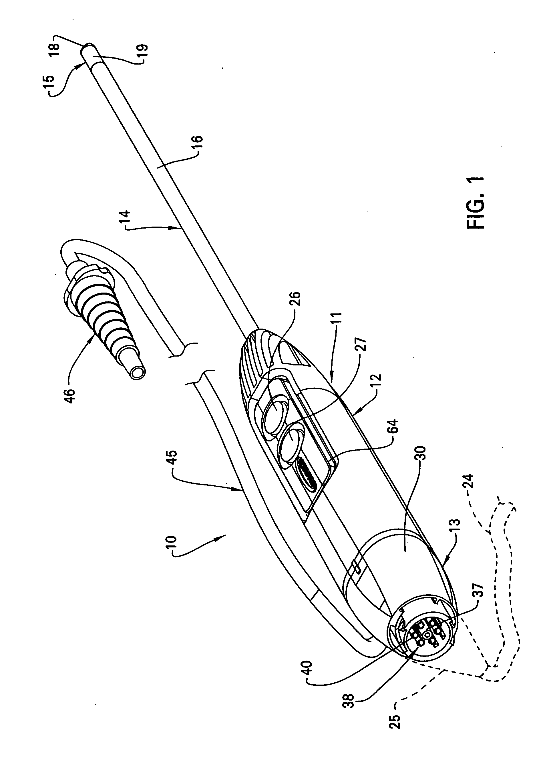
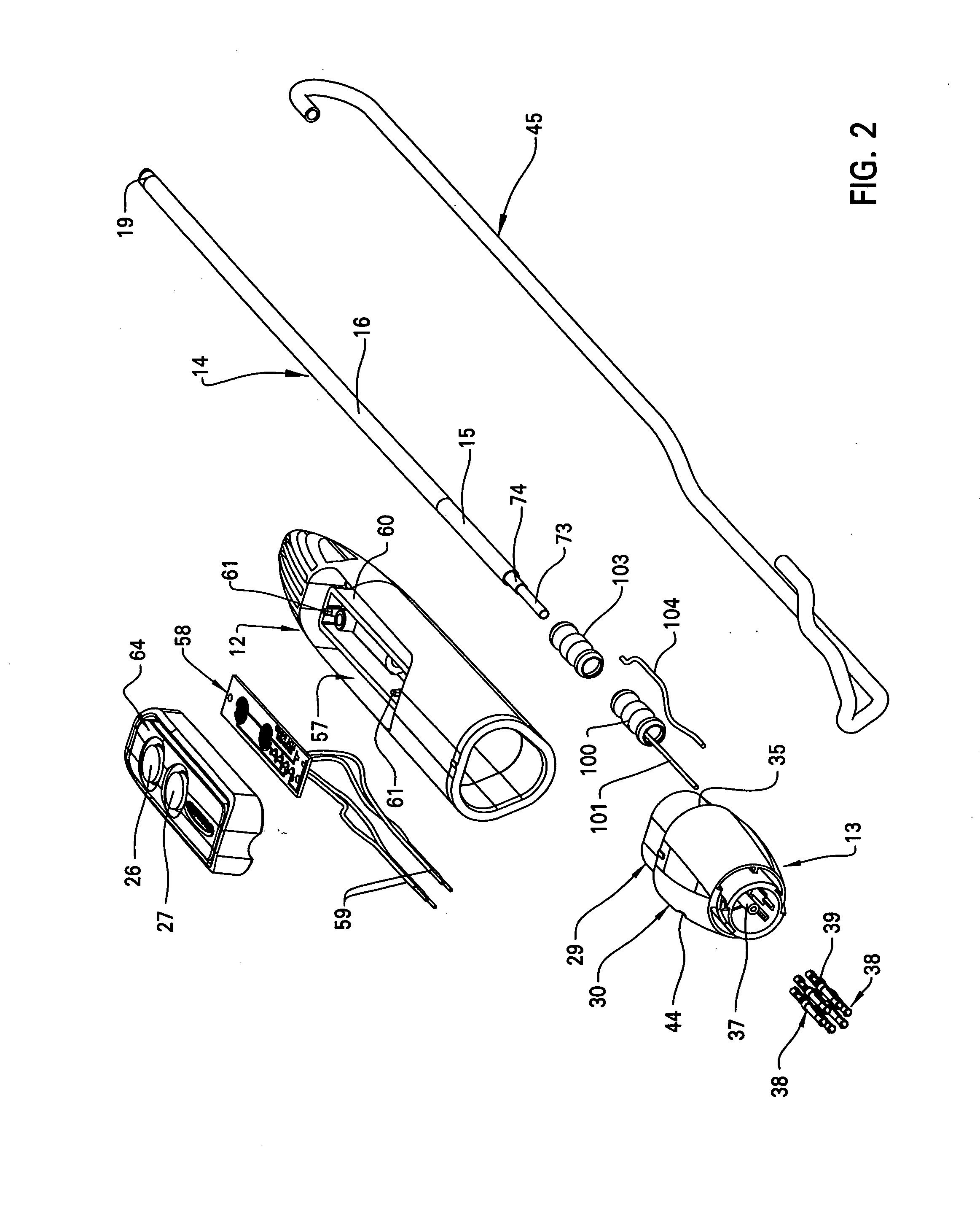
[0030]FIGS. 1 and 2 illustrate the electrosurgical tool 10 according to the present invention. The tool 10 includes an elongated housing 11 which serves as the handle for the tool 10. Housing 11 is defined by a generally nose-shaped, forwardly-oriented member 12 and a rear hub 13 which seats within an open proximal end of member 12. A lumen assembly 14 projects forwardly or distally from the distal end of the nose-shaped member 12. Lumen assembly 14 includes an outer tubular shaft 15 formed from conductive material, such as stainless steel, which outer shaft 15 is covered along a majority of the length thereof by an insulating material, such as a heat-shrink tube 16. The distal end of the lumen assembly 14 incorporates an electrode 18. An exposed distal end 19 of outer shaft 15 defines a return or reference electrode, while electrode 18 defines an active, energy-delivering electrode.

[0031] The current for energizing tool 10 is supplied by a control console (not shown), wherein curr...


PUM


Abstract

An electrosurgical tool for cauterizing or ablating targeted tissue, which tool includes a conductive outer shaft which defines a return or reference electrode, and a conductive inner tube disposed within the outer shaft. The inner tube defines both a suction pathway for removing fluid and / or surgical debris from the surgical site through the distal end of the tool, and a pathway for delivering electrical energy to an active electrode secured to the distal end of the suction tube.

Description

FIELD OF THE INVENTION [0001] This invention generally relates to an electrosurgical tool for ablation and coagulation of body tissues during surgery, and specifically to an electrosurgical tool which additionally provides aspiration or suction at the tip of the tool. BACKGROUND OF THE INVENTION [0002] Electrosurgical tools have been available for many years which employ electrical energy to treat targeted patient tissue in various ways. For example, electrocauterization is utilized to seal off and close blood vessels during surgery to prevent blood loss. In addition, ablation is utilized to vaporize or remove tissue using electrical energy. Electrosurgical probes are typically designed to perform both of these functions, depending upon the type of power supplied thereto. Further, monopolar and bipolar electrosurgical tools have long been available, wherein monopolar tools direct electric current from an active electrode defined on the tool through the patient's body and to a return...

Claims


Application Information

Patent Timeline
IPC IPC(8): A61B18/14
CPCA61B2218/007A61B18/148
Inventor EARLEY, CHRISTOPHERHAMEL, ANDREW
Owner STRYKER CORP
Learn More