
Adjusting device for a camshaft of an internal combustion engine

a technology of internal combustion engine and camshaft, which is applied in the direction of valve arrangements, machines/engines, mechanical equipment, etc., can solve the problems of increasing costs, increasing power output stage, and increasing so as to increase the load torque of the camshaft and high actuation dynamics

Inactive Publication Date: 2006-10-26
DAIMLER AG
View PDF5 Cites 10 Cited by
  • Summary
  • Abstract
  • Description
  • Claims
  • Application Information

AI Technical Summary

Benefits of technology

The invention is an adjusting device for a camshaft of an internal combustion engine that can be used for all applications and phase angle ranges. The device uses a planetary gear mechanism and a brake to adjust the phase angle between the drive element and the output element. The device has a theoretically unlimited actuating range and can be adjusted using a hysteresis brake. The device can be used in all applications and can be adapted by adjusting the transmission ratio of the planetary gear mechanism. The device is designed as two planetary gear mechanisms coupled to each other and has common elements, which results in a narrow design and space-saving arrangement. The technical effects of the invention include improved control and flexibility for adjusting the camshaft timing, reduced space requirement, and improved performance.

Problems solved by technology

However, in order to implement this solution, a two-stage gear mechanism with a high transmission ratio is required, which entails increased costs.
In addition, relatively high currents flow during the adjustment, making a power output stage necessary.
However, the lever mechanism is relatively complex and very sensitive to wear and also only permits a limited adjustment range.
In order to be able to rotate the camshaft for advancing the crankshaft, i.e. accelerate the rotor, a rotational spring is additionally located on the actuating element and its continuously acting torque has to be additionally counteracted by braking when the phase angle is constant or when retarding is desired and this additional braking adversely affects the efficiency of the engine.

Method used


Image

  • Adjusting device for a camshaft of an internal combustion engine
  • Adjusting device for a camshaft of an internal combustion engine
  • Adjusting device for a camshaft of an internal combustion engine

Examples


Embodiment Construction

[0020] For the sake of simplicity, the same reference symbols have been used for the designation of corresponding components in the various figures.

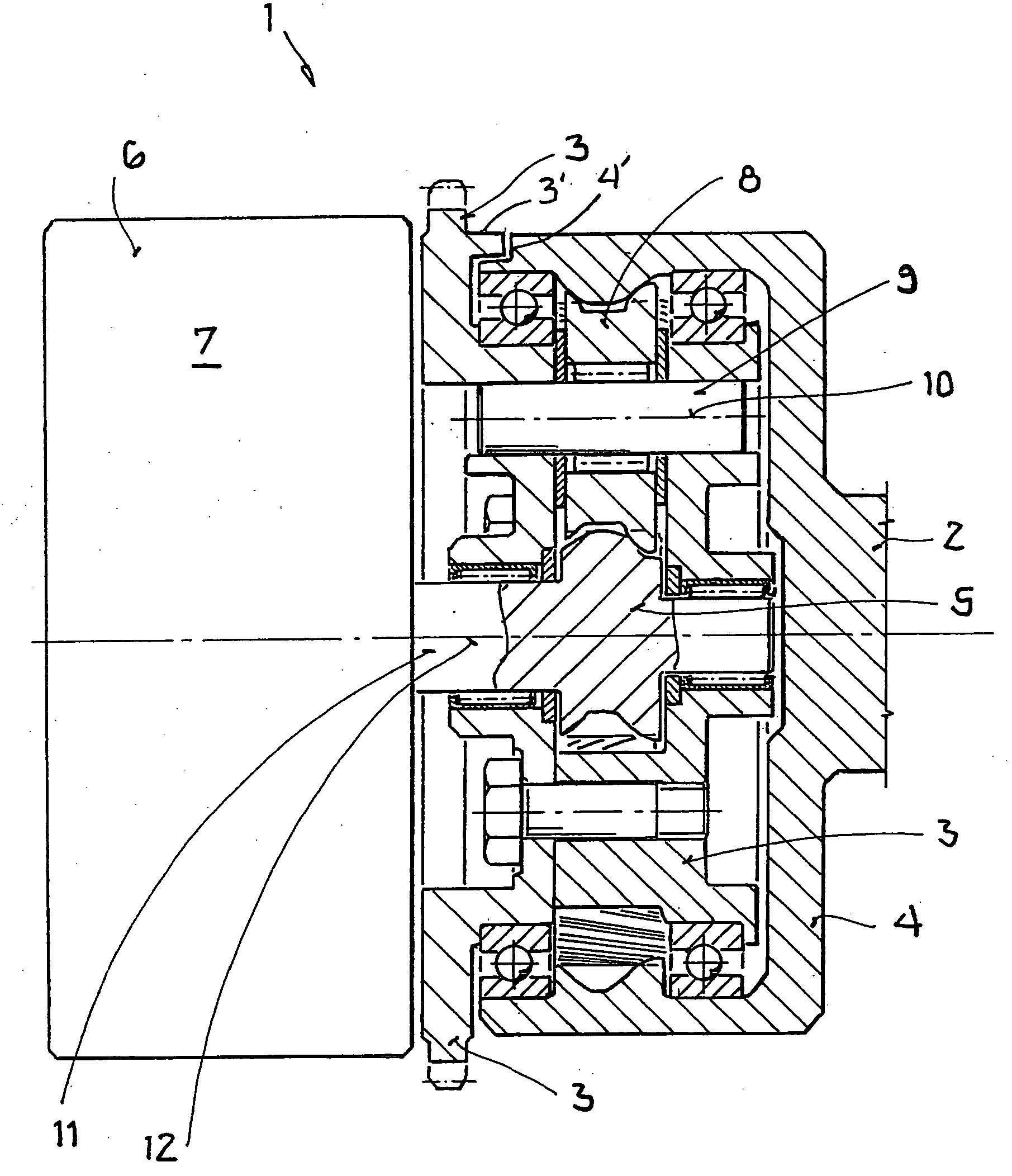
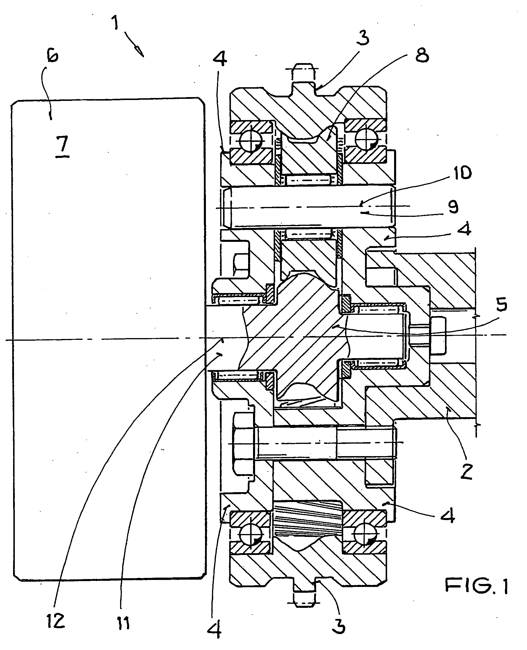
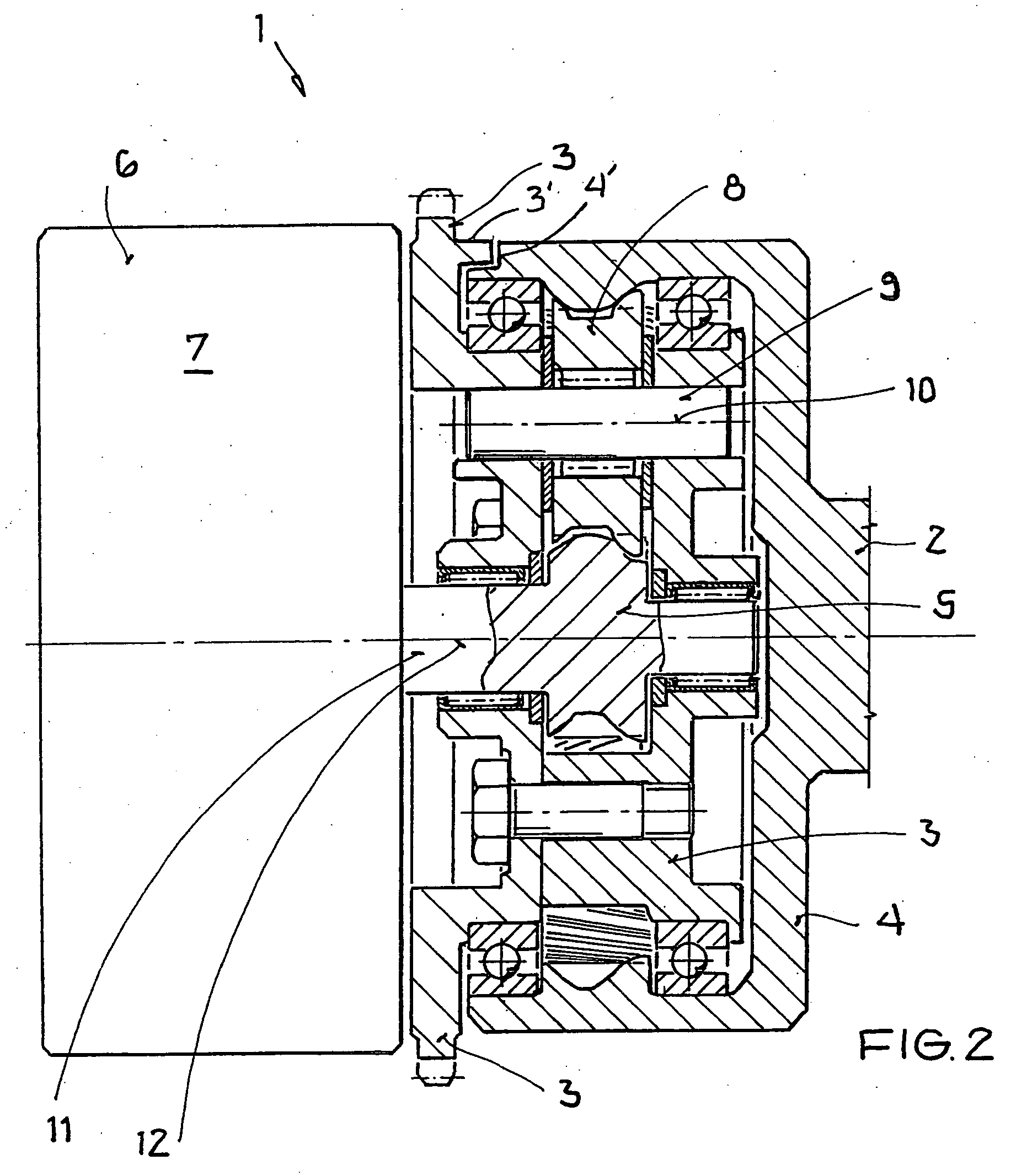
[0021]FIG. 1 shows an adjusting device 1 for a camshaft 2 of an internal combustion engine for changing the phase angle of the camshaft 2 with respect to a crankshaft (not shown here) of an internal combustion engine according to a first exemplary embodiment, the camshaft 2 being driven by the crankshaft by means of the adjusting device 1.

[0022] The adjusting device 1 comprises three elements, specifically, a drive element 3 which is driven by the crankshaft, an output element 4 which is connected fixedly in terms of rotation to the camshaft 2 and which drives the camshaft 2, and an actuating element 5 for adjusting the phase angle between the drive element 3 and output element 4 to which a brake 6 is connected, it being possible to bring about a relative rotation between the drive element 3 and output element 4 by varying the torque a...


PUM


Abstract

In an adjusting device for a camshaft of an internal combustion engine having a drive element which is driven by a crankshaft of the internal combustion engine, an output element which drives the camshaft of the internal combustion engine, and an actuating element controlled by a brake so as to provide for a relative rotation between the drive element and output element by varying the braking torque effective on the actuating element.

Description

[0001] This is a Continuation-In-Part Application of International Application PCT / EP2004 / 012536 filed Nov. 5, 2004 and claiming the priority of German Application 103 55 560.9 filed Nov. 28, 2003.BACKGROUND OF THE INVENTION [0002] The invention relates to an adjusting device for a camshaft of an internal combustion engine with a drive element driven by the crankshaft of the engine and capable of changing the angular position of the camshaft relative to the crankshaft. [0003] DE 100 38 354 A1 discloses an adjusting device for a camshaft of an internal combustion engine which is composed of a planetary summing gear mechanism and an electric servo-motor. One of the two inputs of the gear mechanism is connected to the crankshaft of the internal combustion engine, and the other input is connected to the servomotor. The camshaft is mounted on the output of the gear mechanism. When the rotational speed of the servomotor changes, the rotational speed of the camshaft is changed compared to ...

Claims


Application Information

Patent Timeline
Patent Type & Authority Applications(United States)
IPC IPC(8): F01L1/34F01L1/344F01L1/352
CPCF01L1/352F01L1/344
Inventor GREGOR, MATTHIASMEINTSCHEL, JENSSTOLK, THOMASGAISBERG-HELFENBERG, ALEXANDER VON
Owner DAIMLER AG
Learn More