Eureka AIR delivers breakthrough ideas for toughest innovation challenges, trusted by R&D personnel around the world.

Mode selector mechanism for an impact driver

Inactive Publication Date: 2006-10-26
EASTWAY FAIR
View PDF53 Cites 173 Cited by
  • Summary
  • Abstract
  • Description
  • Claims
  • Application Information

AI Technical Summary

Benefits of technology

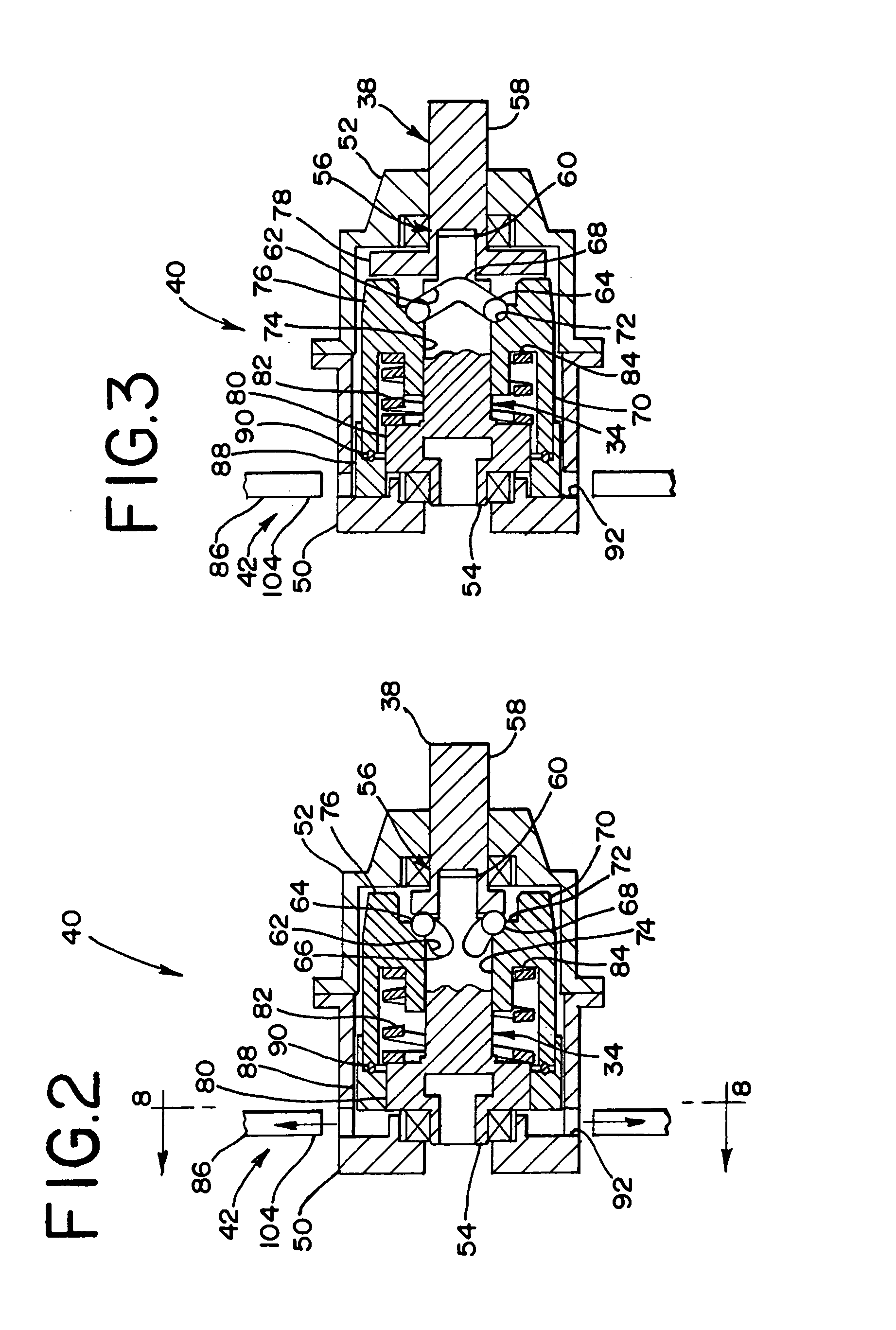
[0007] A mode selector mechanism is described that allows a user to select either an impact mode or a drill mode. The impact mode provides torque pulses to the output shaft when high torque loads are experienced. The drill mode provides generally smooth torque to the output shaft. A clutch that limits the torque to the output shaft may also be used. The mode selector mechanism includes a stopping member that prevents the impact mechanism from disengaging in the drill mode but allows the impact mechanism to disengage and reengage in the impact mode. Additional details and advantages are described below.

Problems solved by technology

The inconsistent speeds of the input and output shafts cause the impact mechanism to impart a rotary impact to the output shaft providing a torque to the output shaft that exceeds the torque limit of the impact mechanism.
However, conventional impact drivers are not universal as a rotary tool because of difficulties associated with using impact drivers in drilling operations.
Specifically, utilization of a conventional impact driver in a drilling operation may inadvertently provide a rotary impact and associated torque to a drill bit that exceeds the load capabilities of the drill bit.
This difficulty is also applicable to smaller driver bits that are utilized in low torque operations.
Likewise, conventional impact drivers are not generally preferred for general purpose driving applications where smooth torque is desired and a torque limiting clutch is used.
However, such prior art drivers are relatively complex with many machined components that require complex manufacturing processes to manufacture and assemble, thus resulting in a relatively high cost power tool.

Method used


Image

  • Mode selector mechanism for an impact driver
  • Mode selector mechanism for an impact driver
  • Mode selector mechanism for an impact driver

Examples


Embodiment Construction

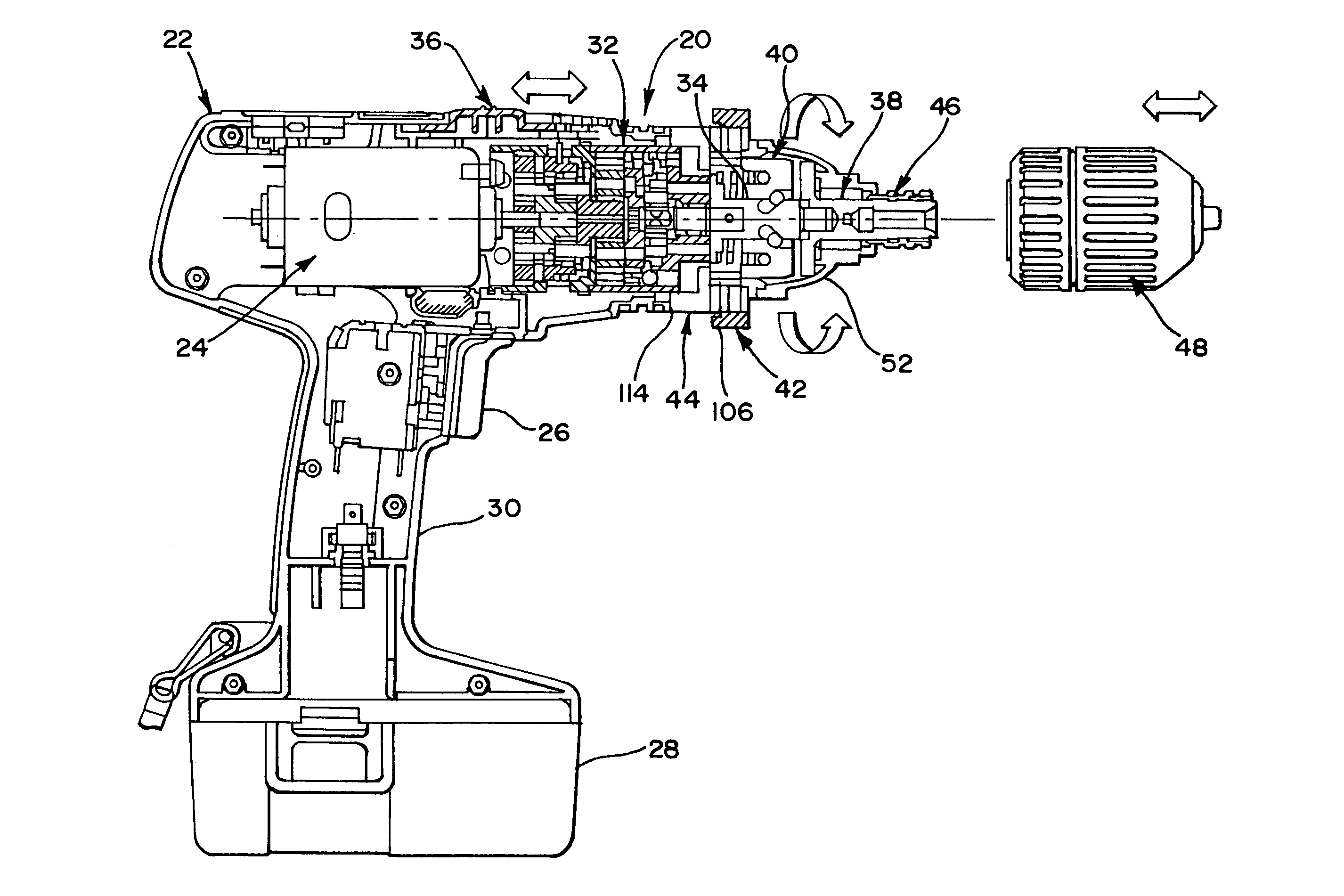
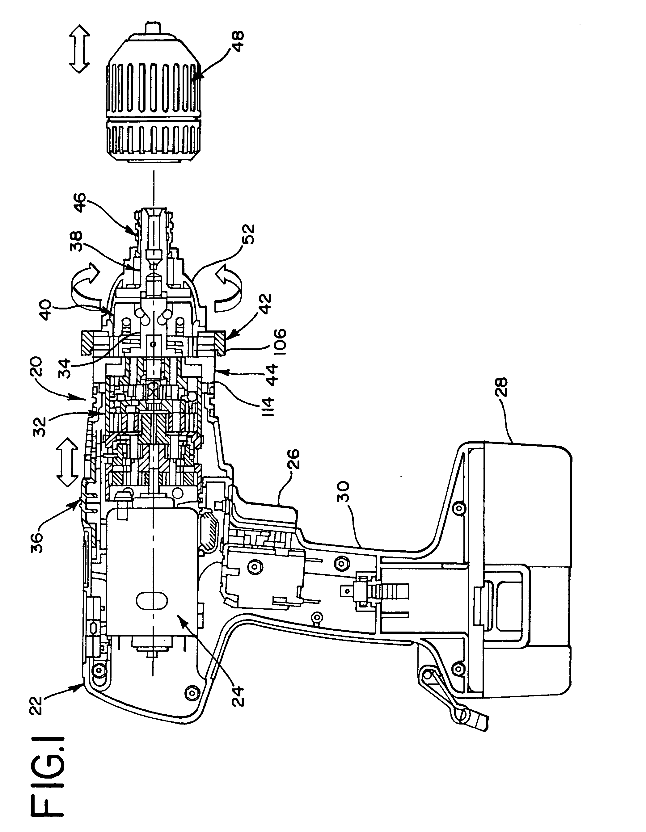
[0035] With reference now to FIG. 1, one embodiment of a rotary power tool is illustrated, characterized as an impact driver and referenced generally by numeral 20. The impact driver 20 includes a housing 22 with a motor 24 oriented therein. The motor 24 is selectively operated by trigger switch 26 for providing power from a power source. The power source is a battery 28 received within a lower portion of a handle 30 of the housing 22. Of course any type of power source may be used with the impact driver 20. The motor 24 drives a gear box 32 that is also oriented within the housing 22 for imparting a reduced rotation to an input shaft 34 that is rotatably mounted within the housing.

[0036] The gear box 32 includes three planetary gear sets for providing three stages of gear reduction. The gear box 32 is also shiftable between a high speed and a low speed via a speed selector 36 for selection between three stage and two stage gear reduction. High speed may be desired for high speed, ...


PUM

PropertyMeasurementUnit
Pressureaaaaaaaaaa
Torqueaaaaaaaaaa

Abstract

A mode selector mechanism is provided for a rotary power tool for selecting between an impact mode and a drill mode. The power tool includes a housing, a motor oriented in the housing, an input shaft and an output shaft both rotationally mounted in the housing. An impact mechanism connects the input shaft to the output shaft for imparting a rotary impact to the output shaft when the torque load exceeds a predetermined torque capacity of the impact mechanism. A stopping member is shiftable by a user between a first orientation that permits the impact mechanism to operate in the impact mode and a second orientation that prevents a coupler of the impact mechanism from retracting, thus maintaining the connection of the input shaft and the output shaft in the drill mode.

Description

BACKGROUND [0001] The invention relates generally to a rotary power tool with a mode selector mechanism, and more particularly to an impact driver with a mode selector mechanism for selecting between an impact mode and a drill mode. [0002] Impact drivers are well known in the art of power tools for providing high torque rotary motion. Impact drivers may be powered by alternating current, direct current, pneumatics or hydraulics. An exemplary prior art impact driver is disclosed in U.S. Pat. No. 6,223,834, which discloses an alternating current powered, corded impact driver, which is incorporated by reference herein. [0003] Impact drivers typically include an impact mechanism for providing an increased output torque upon experiencing a load torque that exceeds a predetermined torque of the impact mechanism. The predetermined torque of the impact mechanism is defined by a biasing member incorporated within the mechanism. Upon experiencing a load torque that exceeds this predetermined ...

Claims


Application Information

Patent Timeline
IPC IPC(8): B23B45/16
CPCB25B21/00B25B23/1405B25B21/02
Inventor SIA, KHIAM KEONGWONG, RAYMOND WAI MANPOON, KING YUZHANG, YANJUNMA, LIGUO
Owner EASTWAY FAIR
Why Eureka
Eureka Blog
Learn More