Brushless motor and recording disk driving apparatus having the brushless motor

a brushless motor and recording disk technology, applied in the direction of dynamo-electric machines, instruments, magnetic circuit shapes/forms/construction, etc., can solve the problems of insufficient inability to obtain sufficient torque of the brushless motor, and insufficient torque needed at the time of starting the brushless motor, so as to reduce the size and thickness of the inner rotor type brushless motor, reduce the current of the brushless motor, and prevent the effect of torque reduction

Inactive Publication Date: 2006-10-26
NIDEC CORP
View PDF8 Cites 11 Cited by
  • Summary
  • Abstract
  • Description
  • Claims
  • Application Information

AI Technical Summary

Benefits of technology

[0006] According to the invention, reduction in the size and thickness of a brushless motor can be realized, decrease in the torque is prevented, and lower current in the brushless motor can be realized.
[0011] In the brushless motor as an example of the invention, a magnetic circuit is formed by the rotor magnet and the annular shield plate, and the magnetic flux of the rotor magnet passes through the magnetic plate and flows in the rotor. Since the magnetic flux of the rotor magnet is not passed to the other members, generation of excessive magnetically attractive force between the rotor magnet and the other members can be suppressed, and current with respect to a predetermined torque can be lowered.
[0012] Since the annular shield plate is located between the magnetically neutral area and the outer circumferential face of the rotor magnet, particularly, part of the magnetic flux flowing to the stator side in the outer circumferential face of the rotor magnet can be prevented from flowing to the annular shield plate. In addition, generation of excessive magnetically attractive force between the rotor magnet and the housing member can be prevented.

Problems solved by technology

However, as the size and thickness of the inner rotor type brushless motor is further reduced, the following problems may occur.
In other words, a magnetic path is formed between the rotor magnet and the magnetic base plate, so that an effective magnetic path between the rotor magnet and the stator decreases, sufficient torque of the brushless motor cannot be obtained, and a start trouble such that the torque necessary at the time of starting the brushless motor is insufficient and the brushless motor does not start may occur.

Method used


Image

  • Brushless motor and recording disk driving apparatus having the brushless motor
  • Brushless motor and recording disk driving apparatus having the brushless motor
  • Brushless motor and recording disk driving apparatus having the brushless motor

Examples


first embodiment

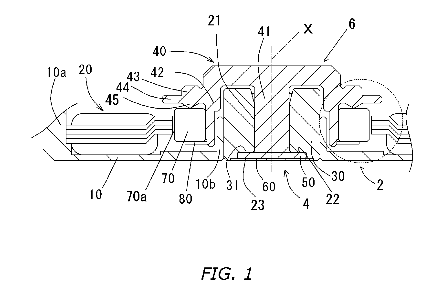
A brushless motor shown in FIG. 1 has a stationary assembly 2, a bearing mechanism 4 for supporting a rotor 6, and the rotor 6 rotatably supported by the bearing mechanism 4.

[0019] The stationary assembly 2 has a first housing member 10 formed by performing plastic working such press on a steel plate made of ferromagnetic material. The first housing member 10 has an annular recess portion 10a which opens upward in the axial direction, and a cylindrical portion 10b formed in the center of the first housing member 10. In the inner circumferential portion of the annular recess portion 10a, a stator 20 is held almost coaxially with the annular recess portion 10a. In the inner circumferential portion of the cylindrical portion 10b, a sleeve 30 having an almost cylindrical shape is held almost coaxially with the cylindrical portion 10b.

[0020] The rotor 6 has a shaft 41 facing the inner circumferential portion of the sleeve 30 over a small clearance, and an almost cup shaped rotor hub 4...

second embodiment

Referring to FIG. 3, a second embodiment of the invention will be described in detail. FIG. 3 shows a modification of the structure of FIG. 2, and a basic configuration is similar to that of the brushless motor of FIG. 1.

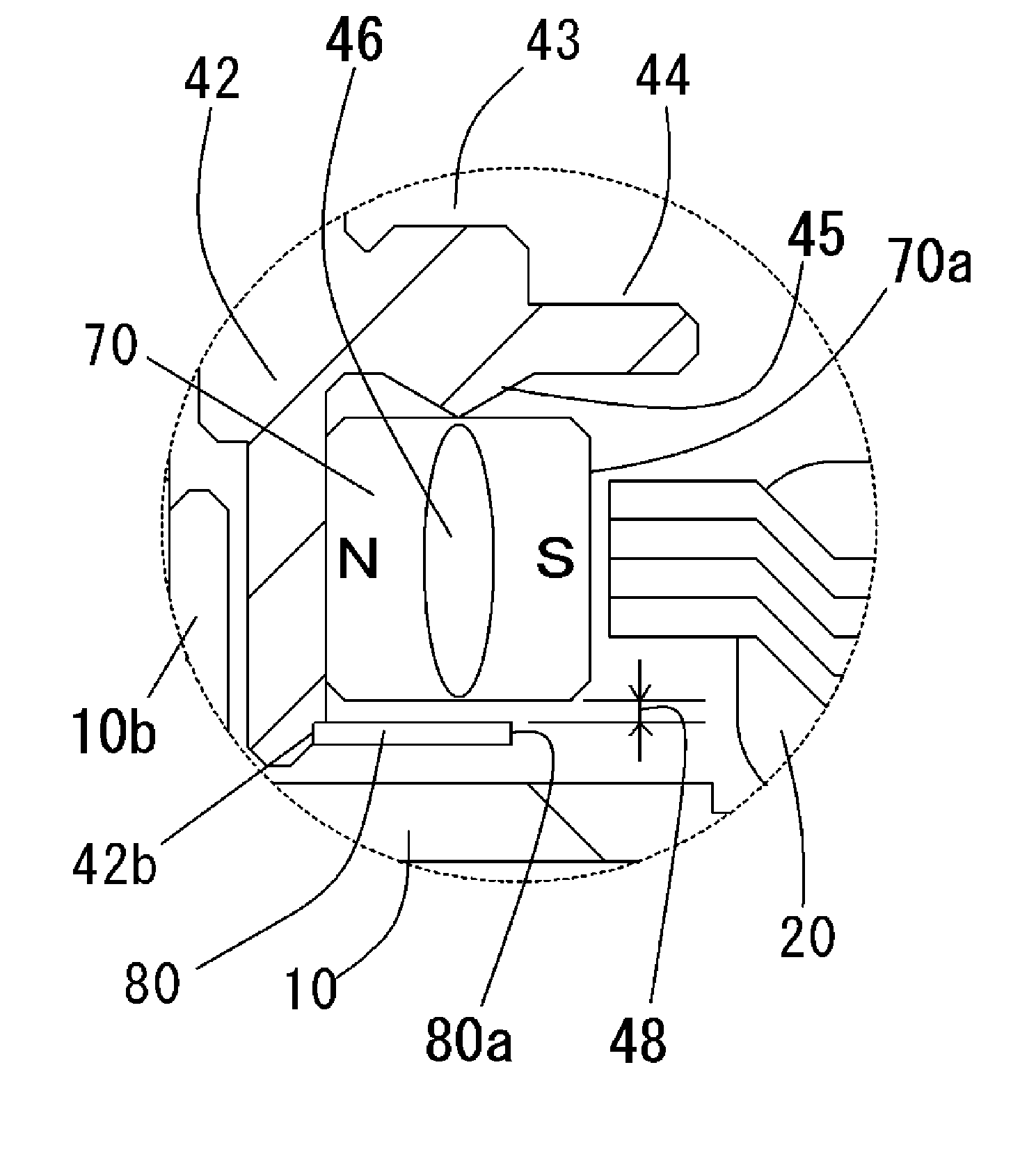
[0041] In a lower end portion of the cylindrical portion 42 of the rotor hub 40, a step 42b for positioning the shield plate 80 in the axial and radial directions is formed. To the step 42b, the shield plate 80 is attached. Between the upper end of the shield plate 80 and the lower end of the rotor magnet 70, a second axially spaced clearance 48 is formed.

[0042] Consequently, the shield plate 80 can be positioned with respect to the rotor 6 at high precision. As a result, coaxiality precision between the rotor magnet 70 and the shield plate 80 can be improved, so that the rotor magnet 70 can be covered at a uniform ratio in the radial direction.

[0043] Further, by attaching the shield plate 80 to the step 42b, the second axially spaced clearance 48 can be formed ...

third embodiment

With reference to FIG. 4, a third embodiment of the invention will be described in detail. FIG. 4 shows a modification of the structure of FIG. 2 and a basic configuration is similar to that of the brushless motor of FIG. 1.

[0045] At the lower end of the cylindrical portion 42 of the rotor hub 40, an annular shield plate 180 and the cylindrical portion 42 are one seamless component. With the configuration, effects similar to those of the foregoing first embodiment can be obtained and the strength of coupling between the cylindrical portion 42 and the shield plate 180 can be increased.

[0046] In the outer part in the radial direction of the disk mounting portion 43, an annular magnetic shield portion 144 extending in the radial direction is attached to the cylindrical portion 42. At the lower end of the magnetic shield portion 144, a projection 145 projecting downward in the axial direction is formed. The projection 145 is in contact with the magnetically neutral area 46 between th...


PUM


Abstract

A brushless motor as an example of the invention has a stationary assembly 2 having a first housing member 10 made of a ferromagnetic material and a stator 20 held in the first housing member 10, and a rotor 6 having a rotor magnet 70 facing the stator 20. A annular shield plate 80 held by the rotor 6 is disposed between the rotor magnet 70 and the first housing member 10 and, further, an outer circumferential face 80a of the shield plate 80 is disposed between a magnetically neutral area 46 in the radial direction in the lower end of the rotor magnet 70 and the outer circumferential face of the rotor magnet 70.

Description

BACKGROUND OF THE INVENTION [0001] 1. Field of the Invention [0002] The present invention relates to a brushless motor and, more particularly, to a small and thin brushless motor for rotating a signal recording / reproducing apparatus. The invention also relates to a recording disk driving apparatus having the brushless motor. [0003] 2. Background Art [0004] In recent years, as a hard disk drive (hereinbelow, called HDD) for recording / reproducing a magnetic disk as a signal recording / reproducing apparatus is becoming smaller, thinner, and more portable, reduction in the size, thickness, and current of a brushless motor mounted on the HDD is in demand. To meet the demand, an inner rotor type brushless motor in which a rotor magnet is disposed on the inner circumference side of a stator is being employed in recent years. [0005] However, as the size and thickness of the inner rotor type brushless motor is further reduced, the following problems may occur. When the size and thickness of t...

Claims


Application Information

Patent Timeline
Patent Type & Authority Applications(United States)
IPC IPC(8): H02K21/12H02K1/00H02K1/27
CPCG11B19/2009H02K21/16H02K1/278
Inventor TAMAOKA, TAKEHITOHIRANO, HIROAKISAICHI, MASAYOSHITAKATERA, JUNICHI
Owner NIDEC CORP
Why Eureka
Try Eureka