
Magnetron for microwave oven

a microwave oven and magnetron technology, applied in microwave heating, electric/magnetic/electromagnetic heating, transit tube leading-in arrangements, etc., can solve the problem of inability to predict an influence, and achieve the effect of reducing the size of the magnetron for the microwave oven, reducing noise, and satisfying safety standards

Active Publication Date: 2006-10-26
PANASONIC CORP
View PDF4 Cites 6 Cited by
  • Summary
  • Abstract
  • Description
  • Claims
  • Application Information

AI Technical Summary

Benefits of technology

"The invention is a magnetron for a small-sized microwave oven that takes safety standards and noise into consideration. The magnetron includes a filter case with a pair of choke coils connected to cathode input conductors and terminals of a capacitor. The design of the choke coil is compact, allowing for a smaller size and a reduction in noise. The size of the filter case is small, and the distance between the choke coil and the filter case is maintained, ensuring safety standards. The invention achieves a decrease in size and a reduction in noise while satisfying safety standards. The microwave oven using this magnetron has a smaller size and lower noise levels."

Problems solved by technology

In other words, it is impossible to predict an influence in the case in which a size is reduced.

Method used


Image

  • Magnetron for microwave oven
  • Magnetron for microwave oven
  • Magnetron for microwave oven

Examples


Embodiment Construction

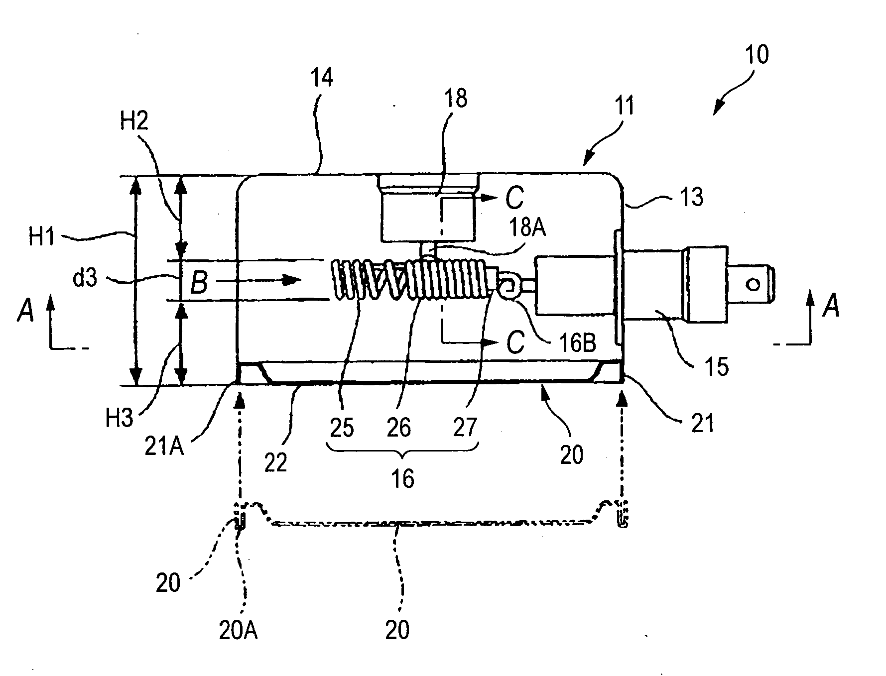
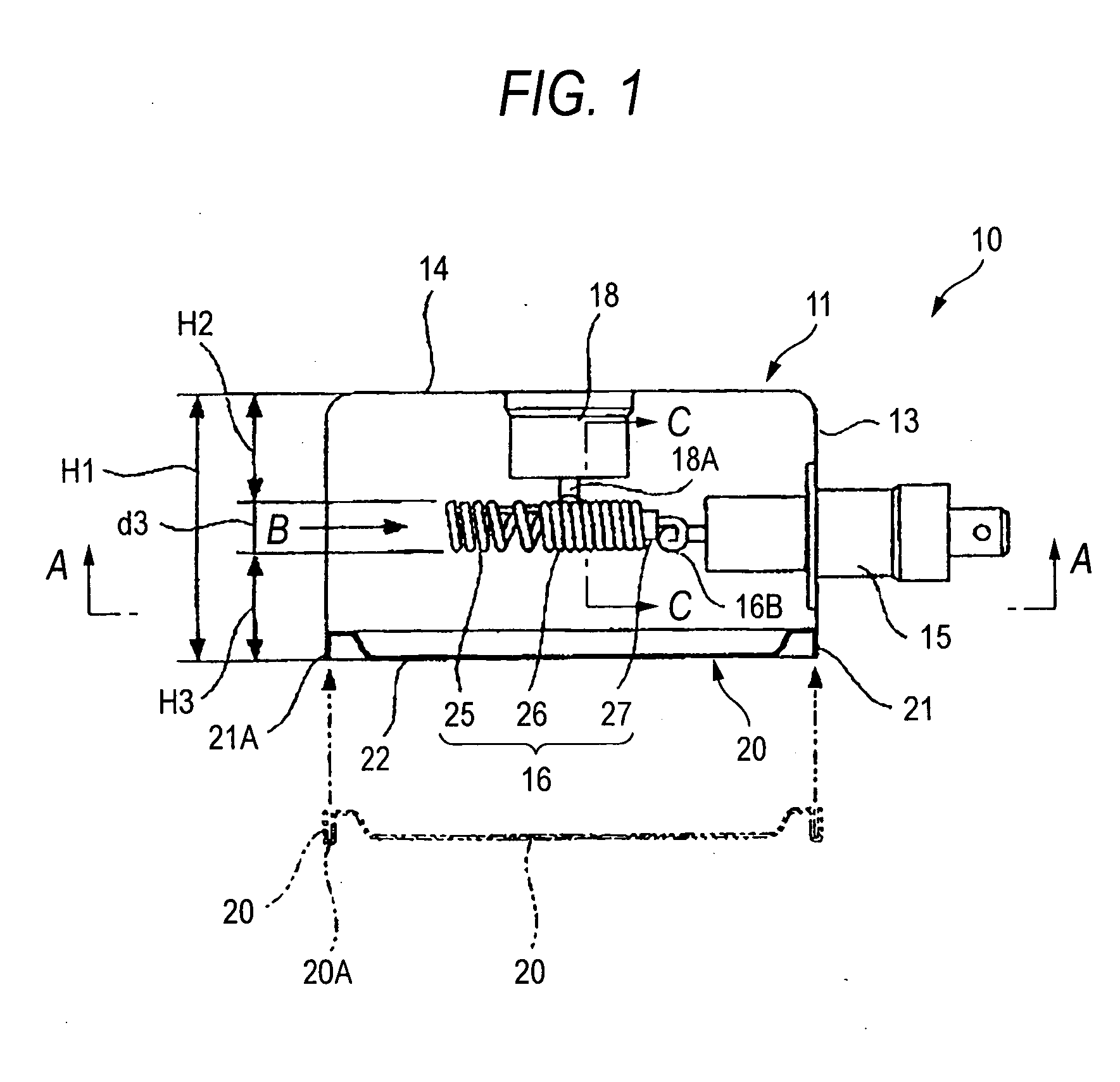
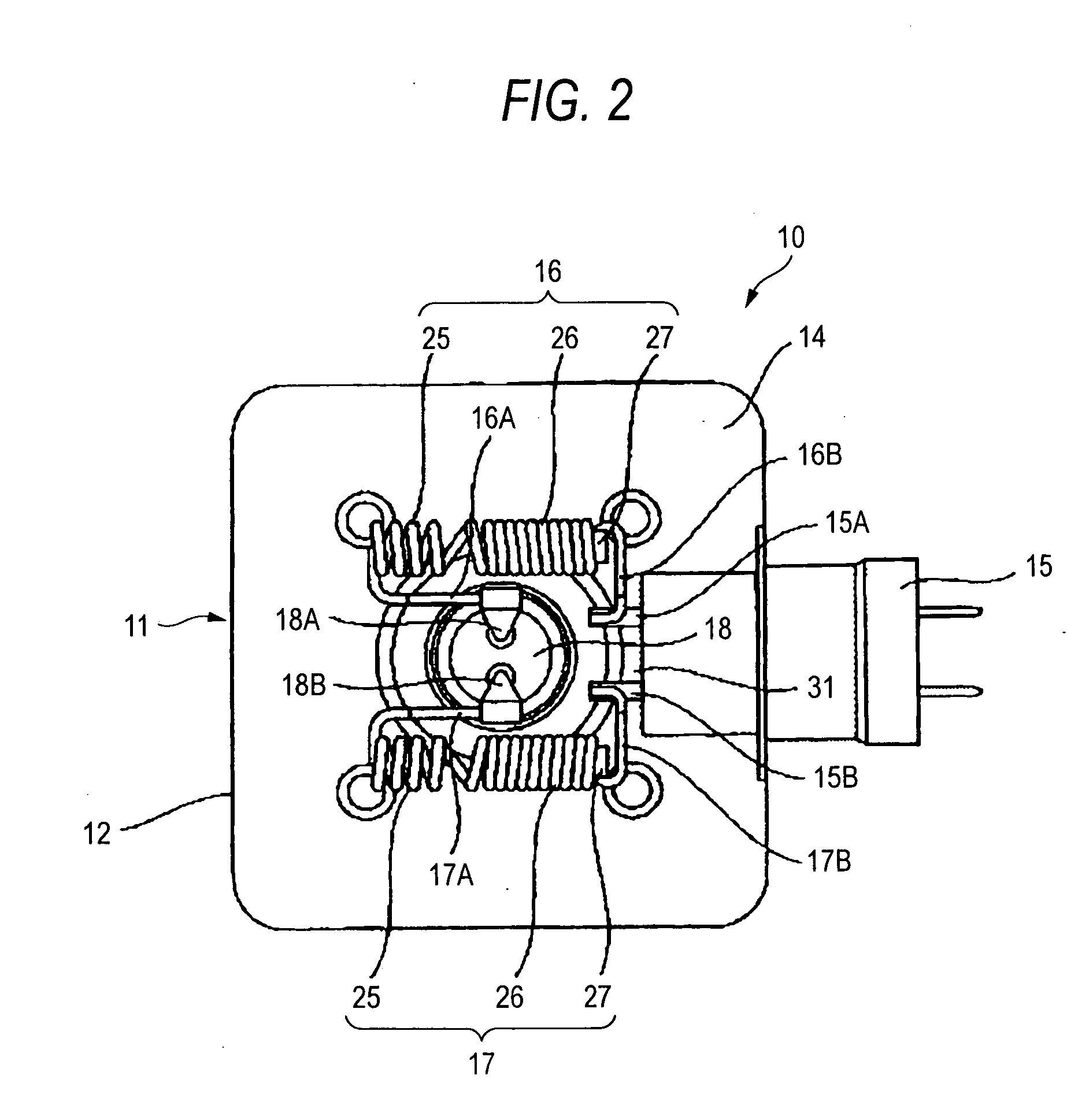
[0029] As shown in FIGS. 1 and 2, a magnetron 10 for a microwave oven according to an embodiment of the invention (which will be hereinafter referred to as a “magnetron 10”) comprises a filter case 11, a capacitor 15 is provided on a side wall 13 of the filter case 11 and a pair of choke coils 16 and 17 are provided in the filter case 11. The choke coils 16 and 17 and the capacitor 15 constitute a so-called LC filter circuit.

[0030] In the filter case 11, a cathode input portion 18 is provided on the center of a ceiling portion 14 of a case body 12, the capacitor 15 is provided on the center of the side wall 13 and the opening of the case body 12 is sealed with a cover member 20.

[0031] The capacitor 15 has a pair of capacitor terminals 15A and 15B protruded into the filter case 11.

[0032] The cathode input portion 18 has a pair of cathode input conductors 18A and 18B protruded into the filter case 11.

[0033] The cover member 20 includes a fitting peripheral wall 21 which can be fit...


PUM


Abstract

It is an object to provide a magnetron for a small-sized microwave oven which takes safety standards and a noise into consideration, in a magnetron 10 for a microwave oven, a pair of choke coils 16 and 17 are provided in a filter case 11, and a height H1 of the internal surface of the filter case 11 is set to be 35 to 45 mm, an outside diameter d3 of an air-core type inductance 25 is set to be 5.5 to 7.5 mm and a sectional area S of a high frequency absorbing member 27 is set to be 5 to 16 mm2. In the magnetron 10 for a microwave oven, an electrostatic capacity between capacitor terminals 15A and 15B and the filter case 11 is increased to be 500 to 700 pF.

Description

BACKGROUND OF THE INVENTION [0001] 1. Field of the Invention [0002] The present invention relates to a magnetron to be used in a microwave oven. [0003] 2. Description of the Related Art [0004] A conventional magnetron for a microwave oven comprises a choke coil 51 in a filter case 50, and has an end 51A of the choke coil 51 connected to a cathode input conductor 52 and the other end 51B of the choke coil 51 connected to a terminal 53A of a capacitor 53, and the capacitor 53 is provided on a side wall of the filter case 50 as shown in FIG. 14. [0005] The choke coil 51 can solve the following problem. More specifically, an air-core type inductance 55 and a core type inductance 56 having a bar-shaped high frequency absorbing member (ferrite core) 57 in a winding are connected in series so that the dielectric breakdown of a winding in the choke coil 51 is burned to cause an insulation failure or the crack of the ferrite core 57 is generated (for example, JP-B-57-17344 Publication). [000...

Claims


Application Information

Patent Timeline
Patent Type & Authority Applications(United States)
IPC IPC(8): H01J25/50
CPCH01J23/15H05B6/72H01J23/54
Inventor OCHIAI, HIROSHISAITOU, ETSUOSUZUKI, YOSHIMASAKUWAHARA, NAGISA
Owner PANASONIC CORP
Learn More