Cooling device incorporating boiling chamber

Inactive Publication Date: 2006-10-26
HON HAI PRECISION IND CO LTD
View PDF16 Cites 28 Cited by
  • Summary
  • Abstract
  • Description
  • Claims
  • Application Information

AI Technical Summary

Benefits of technology

[0006] According to a preferred embodiment of the present invention, a cooling device incorporating a boiling chamber comprises a heat sink, a fan located at one side of the heat sink, a fan duct covering the heat sink and the fan therein, and several pins for securing the cooling device. The heat sink comprises a chamber receiving working liquid therein and a mounting plate located at a bottom surface of the chamber. The working liquid easily evaporates when it receives heat. Two opposite edges of the mounting plate extend beyond two opposite sides of the heat sink. Each edge defines two securing hole

Problems solved by technology

However, as the CPU operates faster and faster, and, therefore generates larger and larger amount of heat, the conventional heat sink, which transfers heat via heat conduction means, cannot meet the increased heat dissipating requirement of the CPU.
However, the conventional boiling chamber cooling device has several disadvantages needing to be improved: 1. the forced airflow generated by the fan of the cooling device cannot be sufficiently utilized to dissipate heat absorbed by the cooling device from the heat-generating el

Method used


Image

  • Cooling device incorporating boiling chamber
  • Cooling device incorporating boiling chamber
  • Cooling device incorporating boiling chamber

Examples


Example

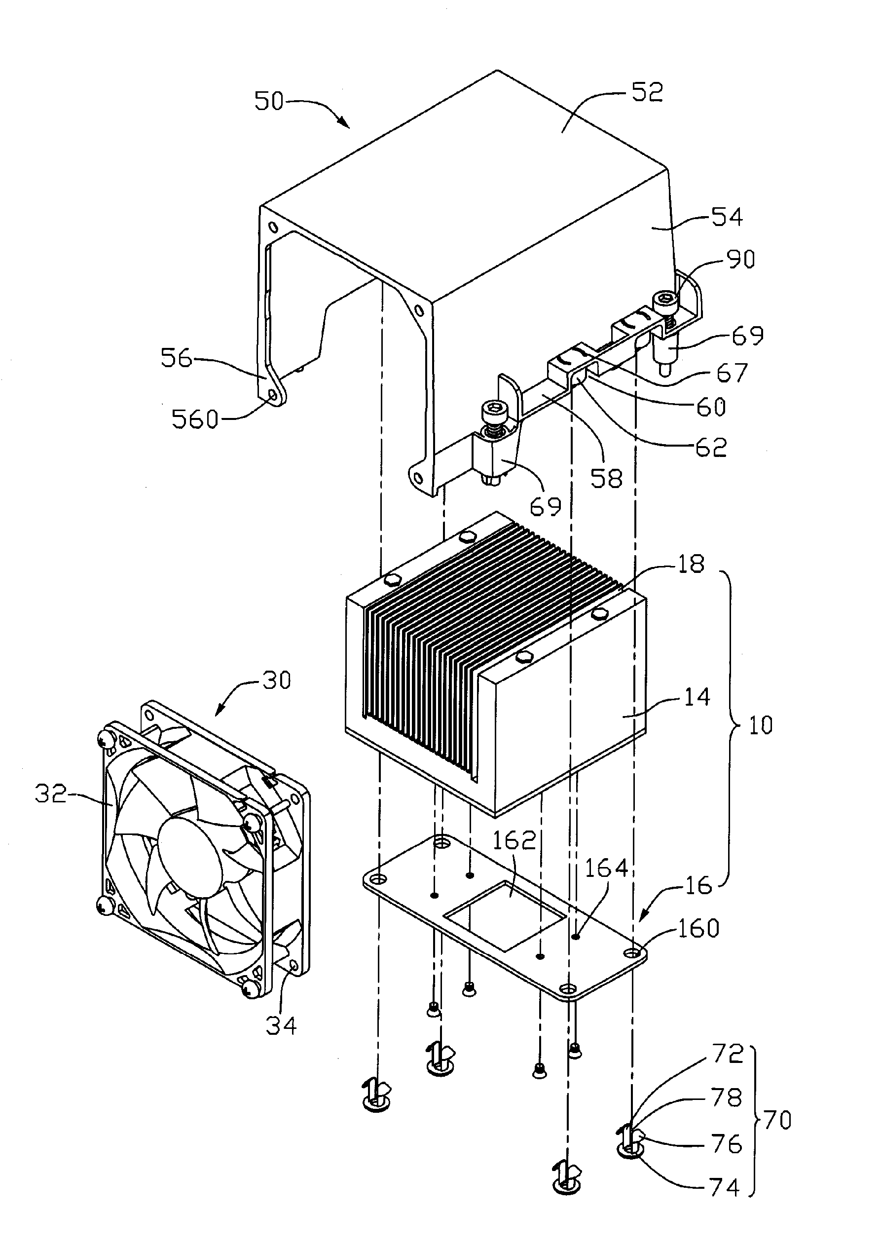
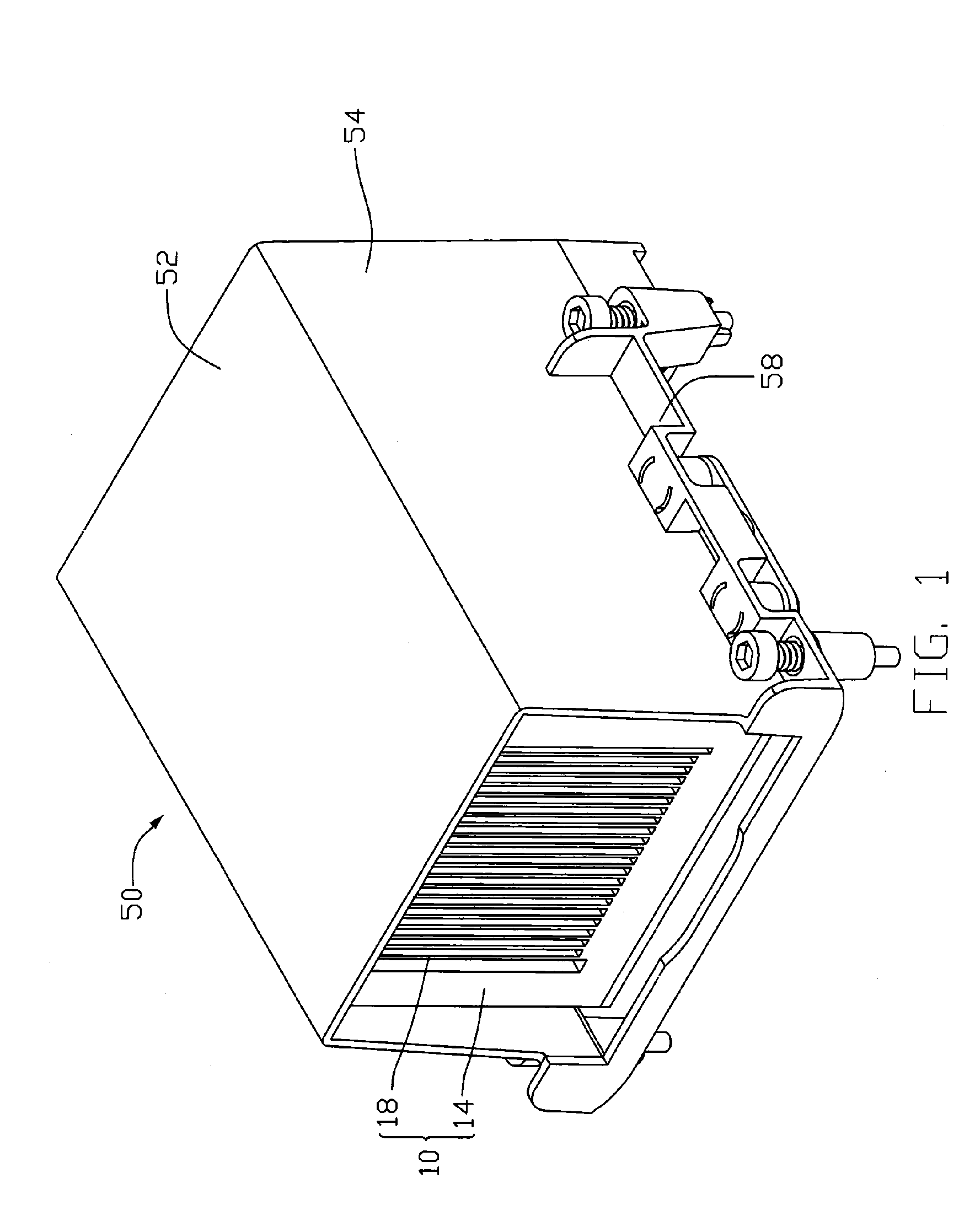
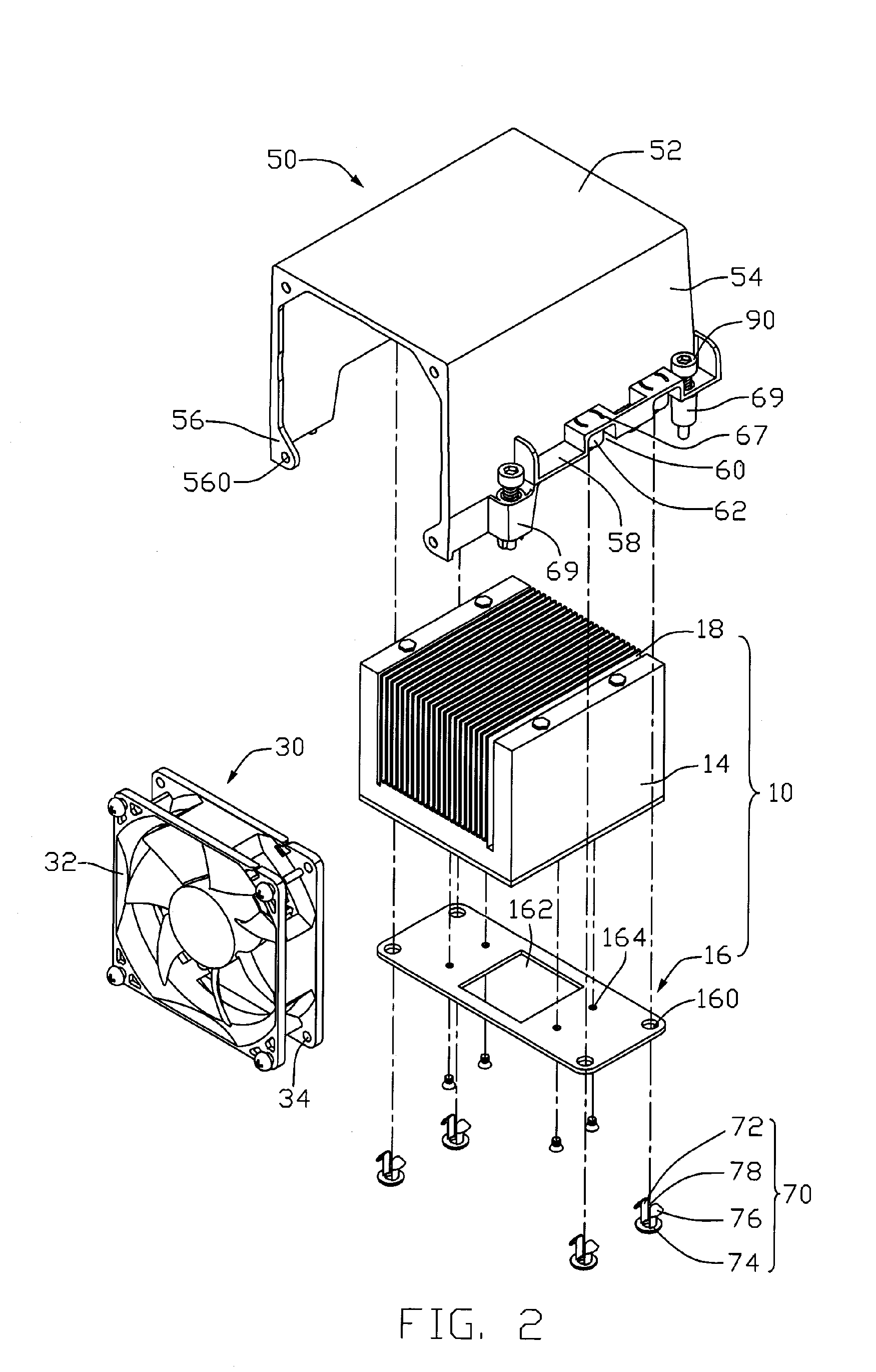
[0015]FIGS. 1-2 show a cooling device incorporating a boiling chamber in accordance with a preferred embodiment of the present invention. The cooling device comprises a heat sink 10, a fan 30 for generating an airflow to the heat sink 10, a fan duct 50 covering the heat sink 10 and fan 30 therein and a plurality of pins 70 for securing the cooling device.

[0016] Referring also to FIGS. 3-4, the heat sink 10 comprises a heat spreader 12 has a bottom surface 120 for thermally contacting with a CPU (not shown), a boiling chamber 14 mounted on the heat spreader 12, a mounting plate 16 connected to a bottom surface of the boiling chamber 14 and surrounding the heat spreader 12, and a plurality of fins 18 arranged on a top of the boiling chamber 14. An air passage 180 is defined between two neighboring fins 18.

[0017] The boiling chamber 14 comprises a bottom wall 20 and a cover 22 hermetically connected to the bottom wall 20 to thereby form a sealed space 24 for containing working liquid...


PUM


Abstract

A cooling device incorporating a boiling chamber includes a heat sink (10), a fan (30) and a fan duct (50) covering the heat sink and the fan therein. The heat sink includes a chamber (14) receiving liquid (26) therein and a mounting plate (16) located at a bottom surface (200) of the chamber. The fan duct is mounted to two opposite edges of the mounting plate. The fan is mounted in a front part while the heat sink is mounted in a rear part of the fan duct. A top wall (220) of the chamber has a plurality of fins (18) extending upwardly therefrom. The liquid has a level higher than that of a bottom surface of the top wall so that a constant contact between the liquid and the top wall is ensured.

Description

FIELD OF THE INVENTION [0001] The present invention relates to a cooling device, and particularly to a cooling device incorporating a boiling chamber. DESCRIPTION OF RELATED ART [0002] As electronic industry continues to advance, electronic components such as central processing units (CPUs), are made to provide faster operational speeds and greater functional capabilities. When a CPU operates at a high speed, its temperature frequently increases greatly. It is desirable to dissipate the heat generated by the CPU quickly. To solve this problem of heat generated by the CPU, a cooling device is often used to be mounted on the top of the CPU to dissipate heat generated thereby. [0003] A conventional cooling device comprises a heat sink with a base for thermally contacting with the CPU to absorb heat therefrom and a fan mounted on the heat sink for generating forced airflow to the heat sink. For enhancing the heat dissipation capability of the heat sink, a heat spreader is arranged betwe...

Claims


Application Information

Patent Timeline
IPC IPC(8): H05K7/20
CPCH01L23/427H01L23/467H01L2924/0002H01L2924/00F28D15/0233F28F3/048
Inventor LIU, TAY-JIAN
Owner HON HAI PRECISION IND CO LTD
Why Eureka
Try Eureka