
Camera module

a camera module and module technology, applied in the field of camera modules, can solve the problems of affecting work efficiency, affecting the reliability of electric connection, and complex processing of mounting the camera module on the mounting board, and achieve the effect of increasing efficiency

Inactive Publication Date: 2006-10-26
SHINKO ELECTRIC IND CO LTD
View PDF7 Cites 20 Cited by
  • Summary
  • Abstract
  • Description
  • Claims
  • Application Information

AI Technical Summary

Benefits of technology

[0014] An object of the invention is to provide a camera module, having an autofocus function, for which the mounting operation can be simplified, and for which the reliability of an electric connection to a mounting board can be improved.
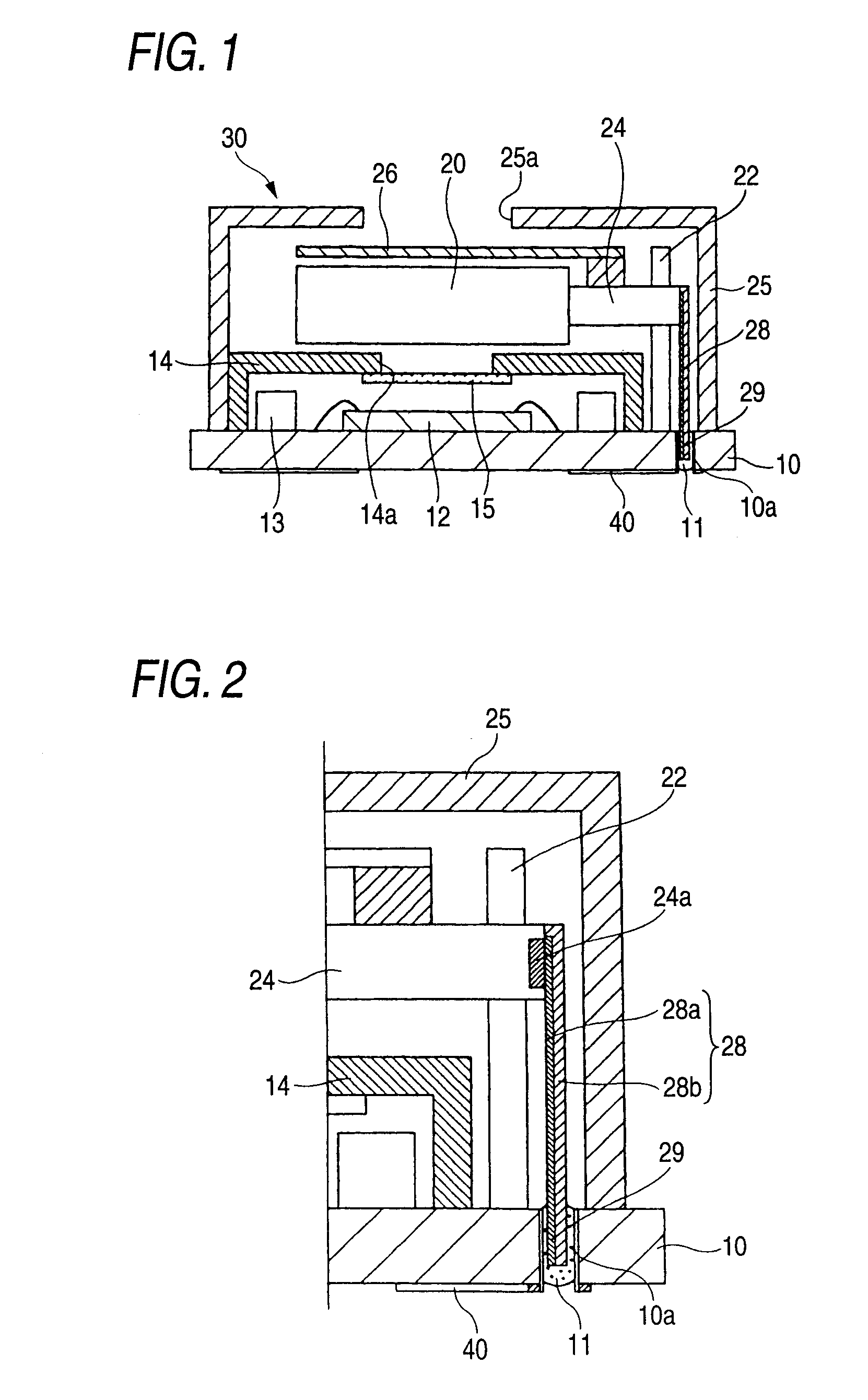
[0018] The image pickup device, the camera optical system and the driver are stored in a case attached to the board, and the flexible wiring board is arranged in the case. Thus, the camera module can be made compactly, and the operation for mounting the camera module can be simplified.
[0019] Further, the camera optical system and the driver are formed as an autofocus unit, and the driver that is incorporated in the autofocus unit and the connection terminal are electrically connected via the flexible wiring board. Therefore, the camera module can be downsized even further, and imaging using auto-focusing can be performed easily.
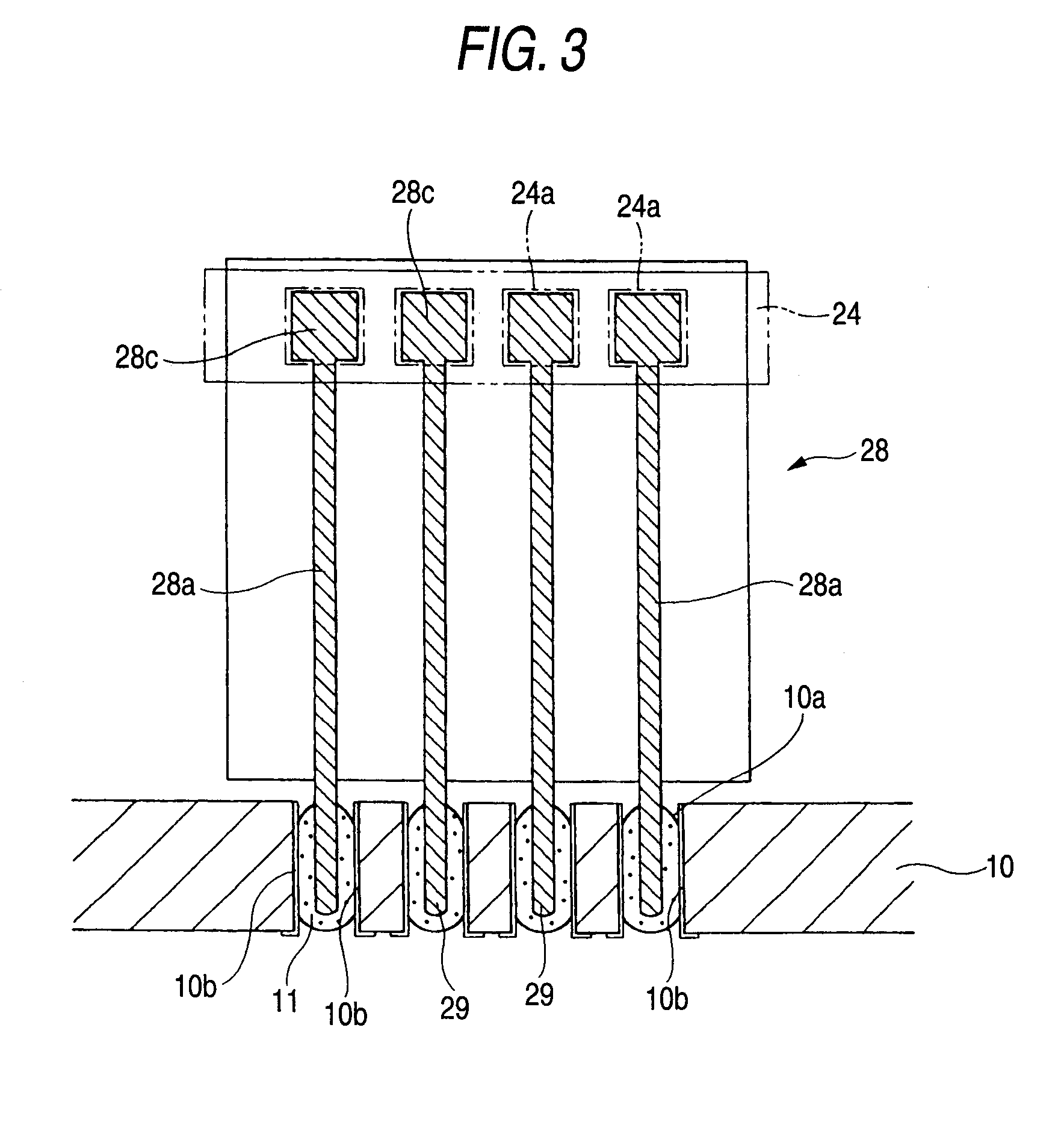
[0023] According to the camera module of the invention, the connection terminal is formed on the mounting face of the board on which the image pickup device and the camera optical system are mounted, and the connection terminal is electrically connected to the driver that drives the camera optical system via the flexible wiring board. Therefore, the operation for mounting the camera module on the mounting board and electrically connecting the driver to a connection electrode on the mounting board can be easily performed. Therefore, the efficiency with which the camera module can be mounted can increase the efficiency with which other electronic parts are manufactured.

Problems solved by technology

As a result, the processing for mounting the camera module on the mounting board becomes complicated.
However, these connection methods adversely affect work efficiency, and when the flexible wiring board and the connection terminal of the mounting board are connected using one of these methods, the reliability of the electric connection is not always satisfactory.

Method used


Image

  • Camera module
  • Camera module
  • Camera module

Examples


Embodiment Construction

(Configuration of a Camera Module)

[0033] The preferred embodiment of the invention will now be described in detail while referring to the accompanying drawings.

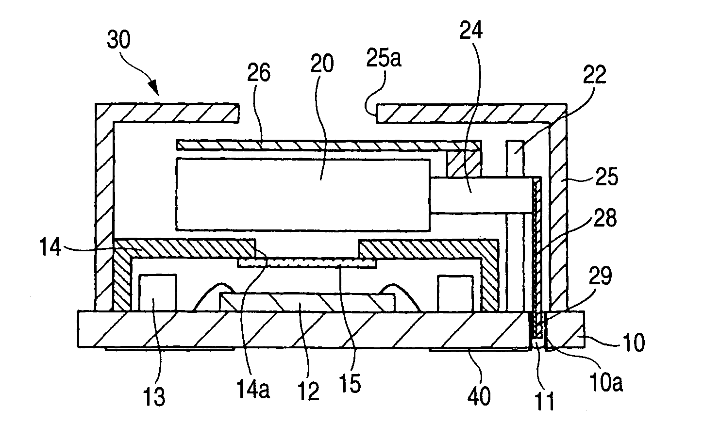
[0034]FIG. 1 is a cross-sectional view of the arrangement of a camera module according to the exemplary, non-limiting embodiment of the invention. The structures of a board 10, an image pickup device 12 and an autofocus unit 20 for a camera module 30 for this embodiment are the same as those for the related-art camera module 5 in FIG. 9, which has an autofocus function and a shutter function.

[0035] That is, the image pickup device 12 is mounted on one side of the board 10, and a chip 13 is peripherally positioned relative to the image pickup device 12. A box shaped inner case 14 is attached to enclose the image pickup device 12 and the chip 13, and an opening 14a is formed in the inner case 14, along the light axis of the image pickup device 12, while an infrared reduction filter 15 is fitted over the opening 14a on the i...


PUM


Abstract

A camera module is provided wherein an image pickup device, a camera optical system and a driver, for aligning and focusing the camera optical system, are mounted on a board; wherein a connection terminal, to be electrically connected to the driver, is formed on a mounting face of the board; and wherein the connection terminal formed on the board is connected to the driver via a flexible wiring board.

Description

[0001] The present application claims foreign priority under 35 USC 119 based on Japanese Patent Application No. 2005-127978, filed Apr. 26, 2005, the content of which is incorporated herein by reference. BACKGROUND OF THE INVENTION [0002] 1. Technical Field [0003] The present invention relates to a camera module, and relates more particularly to a camera module having an autofocus function. [0004] 2. Related Art [0005] Various models are available of camera modules on which an image pickup device, such as a CCD or a CMOS, is mounted (see, for example, patent documents 1 and 2). For these camera modules, not only are fixed-focused products available, but products having an autofocus function have also begun to be provided. [0006]FIG. 9 is a diagram showing an example configuration for a camera module that includes an autofocus function and a shutter function. A camera module 5 comprises: an image pickup device 12, mounted on a board 10; and an autofocus unit 20, located on the incid...

Claims


Application Information

Patent Timeline
IPC IPC(8): G03B13/18
CPCH04N5/2254H04N5/2257H05K1/147H05K1/141H04N5/23212H04N23/54H04N23/57
Inventor SHIRAISHI, SATOSHIKAZAMA, YOICHIFURUKAWA, TOMOHIROKOJIMA, TOMINARI
Owner SHINKO ELECTRIC IND CO LTD
Learn More