
Vehicle for placing railcars on railway tracks

a technology for railcars and railway tracks, applied in the direction of transportation items, load transportation vehicles, transportation vehicles, etc., can solve the problems of axles not fitting the rails precisely, the axle cannot be precisely aligned, and the length of the axle cannot be increased

Inactive Publication Date: 2006-10-26
TRESCOTT WILLIAM BERNARD
View PDF4 Cites 7 Cited by
  • Summary
  • Abstract
  • Description
  • Claims
  • Application Information

AI Technical Summary

Benefits of technology

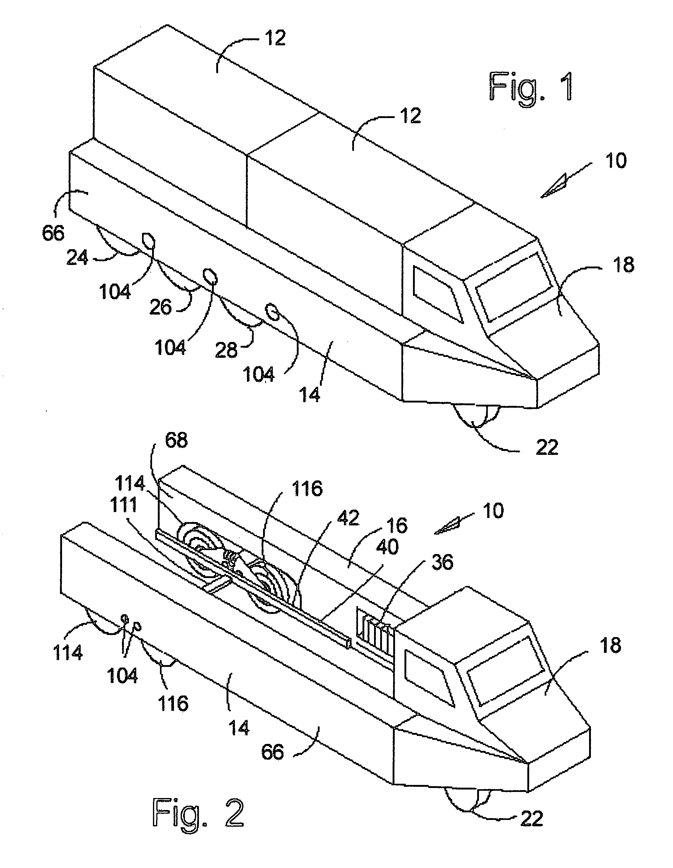
[0010] The vehicle for placing railcars on railway tracks of my invention comprises a U-shaped frame with flexible side structures or beams which may be made of crash absorbent material and equipped with an adjustable toe-angle, variable height suspension. Railway vehicles are attached between the side structures or beams of the vehicle. The variable height front and rear suspension allows railway vehicles to be lifted off the tracks. The rear suspension also has a variable toe angle to control the spread of the flexible beams so it can back around a railway vehicle and then squeeze or grasp the vehicle so that it can be tightly secured while being lifted.
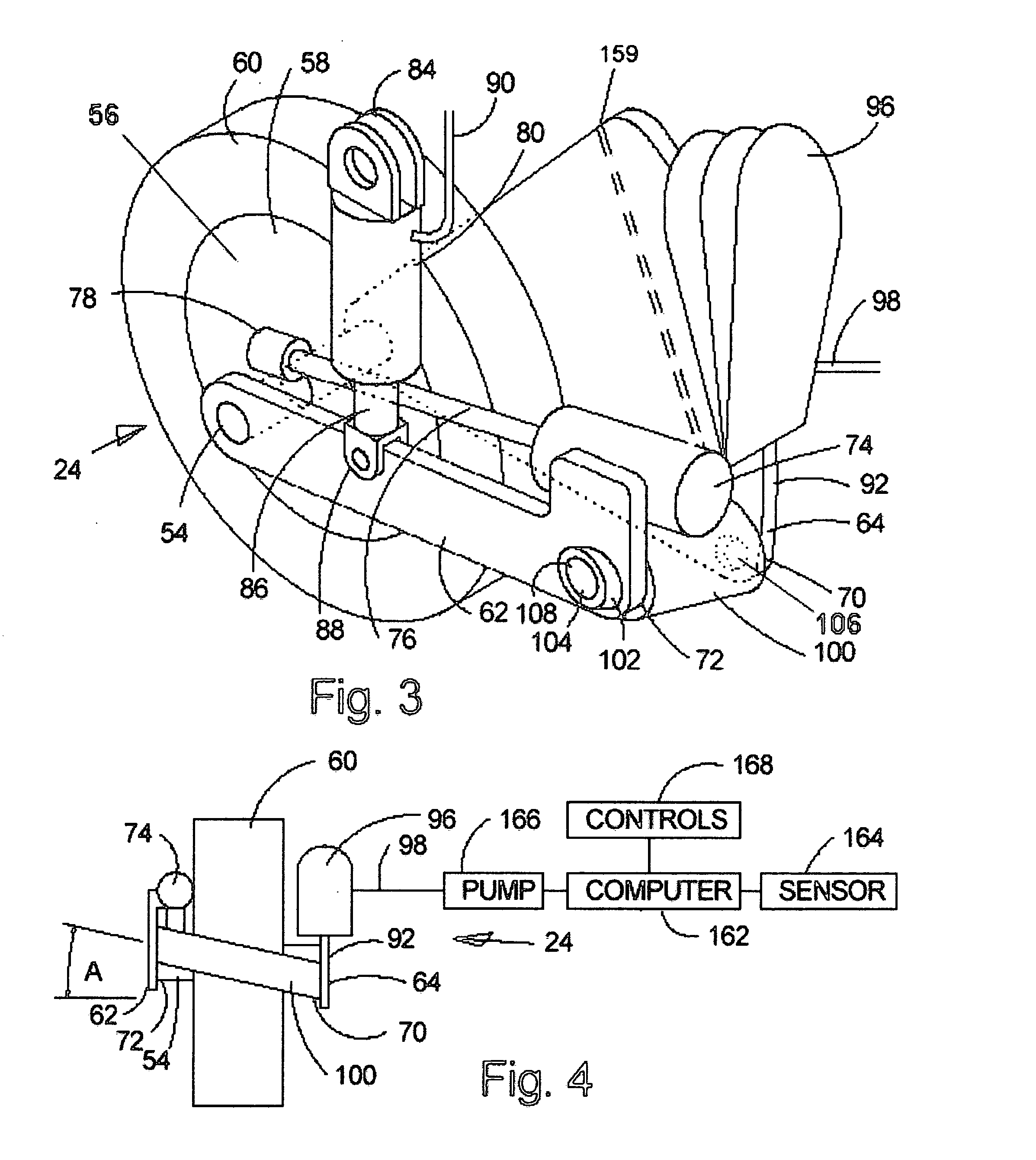
[0011] The vehicle for placing railcars on railway tracks has a wider than normal wheel base, low center of gravity, and crash absorbent side structures which will significantly improve highway safety. Heavy batteries for regenerative braking can be installed in the side structures to enhance crash absorbency. The variable height rear suspension of the vehicle may have a trailing beam design. Rear wheel axles can be mounted on one trailing beam or arm (like an aircraft landing gear), or two beams or arms (like the rear wheel of a mountain bicycle or motorcycle). Regardless of the number of arms, the angle of the pivot where the trailing arms are attached to the side structures of the vehicle is not level with the ground. The pivot bearing is angled so that the outer end is higher than the inner end so that when the vehicle is lowered close to the ground, the rear wheels develop slight toe-out and when the vehicle is raised above its normal ride height, the rear wheels develop slight toe-in. Thus, when the vehicle is lowered close to the ground, the side structures or beams spread apart when driven forward and toward each other when driven in reverse to allow the grasping and releasing of railway vehicles carried between the beams. When the vehicle is raised to a higher than normal ride height, the rear wheels develop toe-in and the side structures or beams of the vehicle spread apart when driven in reverse to steer around the front of a railway vehicle prior to lowering the vehicle to grasp it. They can also squeeze railway vehicles when driven forward to help secure them during an off road collision avoidance maneuver. A control means similar to the joystick of an airplane alters the height of the vehicle through a computer. By controlling ride height and direction, the driver can spread the side structures apart or pinch them together at will to grasp and release railway vehicles.
[0012] An improvement over my prior art is increased facility to precisely control the vehicle's lean or angle of tilt using a superior control means such as a joystick. This allows the wheels of railway vehicles to be placed on one track at a time—a feature not needed on vehicles used primarily for lifting intermodal shipping containers. Moving the joystick to the side leans the truck and at the same time changes the toe angle of the rear wheels so that as the truck leans, the rear wheels are made to steer in the same direction rather than developing toe-in or toe-out as happens when the height of the vehicle is changed. By steering with the rear wheels as well as the front, the vehicle can be made to move in a diagonal direction across the track while the vehicle itself is aligned with the track, thus allowing more than one rail axle to be engaged with a rail simultaneously.
[0013] One knowledgeable in the art will recognize that whenever wheels mounted on articulated bogies are misaligned, tilting a rail vehicle will cause the wheel lower to the ground to also be closer to the track, thus if the lower wheel of a bogie is correctly positioned on a rail, the other wheel(s) on the same side of the bogie can be brought into proper position on the same rail by lowering the entire vehicle while simultaneously moving it toward the rail, causing the bogie to swivel into proper alignment. All of the wheels on one side of a multi axle rail vehicle or group of rail vehicles can thus be placed on one rail at once, despite being mounted on articulated rail-trucks or bogies that may not initially be aligned with the tracks. A video camera is provided underneath the cab of the truck so that the operator can see if the wheels are correctly positioned and, if necessary, make necessary corrections by moving the joystick and the vehicle's steering wheel to obtain proper alignment. The vehicle is equipped with a further control means such as special joystick buttons to operate the front and rear suspensions independently or differentially to control the fore and aft pitch of the vehicle in much the same way as pitch is controlled in an aircraft. The vehicle's steering wheel, similar to that of ordinary trucks, can be turned to adjust the yaw of the vehicle with respect to the track, thus the vehicle can be precisely oriented on three axes independently of the direction of the vehicle's travel. Once all of the wheels on one side of a rail vehicle or group of rail vehicles are positioned on a rail, one skilled in the art will recognize that the wheels on the other side of the rail vehicle(s) will automatically be aligned with the other rail. The control means or joystick can then be moved to a neutral position to level the rail vehicle(s), thus causing all of the rail wheels to become mounted precisely on the track. This is an improvement over the prior art because the entire operation can be performed in less than a minute without auxiliary equipment such as springs or other mechanical means to bring the rail trucks or bogies into alignment.

Problems solved by technology

One skilled in the art will recognize that it is usually not possible for more than one rail axle to be positioned directly above the rails so as to simultaneously engage the track when a vehicle is moved across the rails diagonally.
Single rail axles may work well with the smaller bimodal vehicles shown by Wannamaker, but on longer bimodal vehicles, a misalignment can occur when the vehicle travels around a curve in the track.
The rail axle may cease to be perpendicular to the rails as the vehicle turns, causing a gap or looseness to occur between the track and the wheel flanges so that the axle no longer fits the rails precisely.
Because both the track and wheel flanges are usually made of solid inflexible material such as steel, jarring vibrations can occur when the wheel flanges contact the sides of the rails, possibly damaging cargo and loosening the spikes that hold the track to the railroad ties or sleepers, which one knowledgeable in the art will recognize could result in a catastrophic derailment.
Such a system may work well on a siding or in a rail yard, but abandoning large vehicle components on railway tracks creates a hazard to other trains that might collide with the detached rail-trucks or bogies if they are inadvertently left in the wrong place.
This would be especially hazardous to magnetically levitated trains that travel at very high speeds because magnetic levitation tracks are usually not equipped with switches or sidings to allow such vehicles to travel around obstructions.
Nevertheless, it is still difficult to provide a vehicle that can be easily driven around a relatively long object such as a railcar.

Method used


Image

  • Vehicle for placing railcars on railway tracks
  • Vehicle for placing railcars on railway tracks
  • Vehicle for placing railcars on railway tracks

Examples


Embodiment Construction

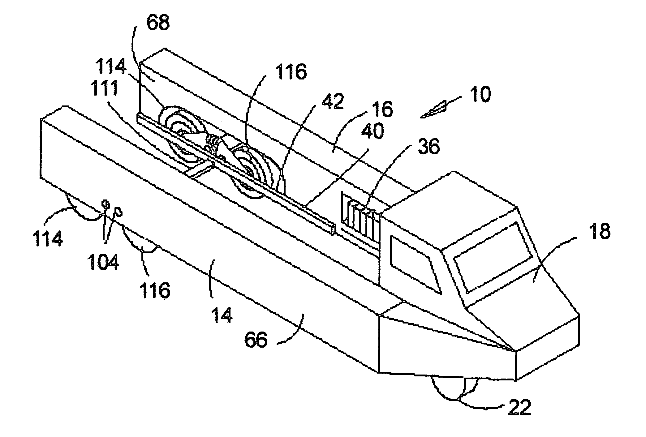
[0028] I will now describe the preferred embodiment of my invention with reference to the accompanying drawings, wherein like numerals are used to refer to like parts. FIG. 1 shows a perspective view of a vehicle 10 according to my invention. The vehicle 10 supports one or more railway vehicles 12 on two parallel bendable beams 14&16. The beams extend rearwardly from a cab 18. The cab comprises an operator's compartment where control apparatus for an operator are located (not shown) and has steerable wheels 22, controlled by the operator, and other standard features well known in the art. The vehicle may be powered by various means, such as by diesel or gasoline engines, by front or rear wheel drives, or by other well known means. In my preferred embodiment, a Diesel-electric or turbo-electric may be used. Rear wheel assemblies 24, 26, 28, 114, &116 may be equipped with either direct electric drive, electric drive with planetary reduction, worm drive, or ring and pinion gear drive a...


PUM


Abstract

A U-shaped vehicle with flexible beams equipped with an adjustable toe-angle, variable height suspension. Railway vehicles are attached between the beams of the vehicle. The rear suspension has a variable toe angle to control the spread of the beams so the vehicle can back around railway vehicles. Rear wheel axles are mounted on arms connected to pivot points. An axle and its pivot points are non-coplaner. The pivot points are angled so that an outer pivot point is higher than an inner pivot point. When the vehicle is lowered close to the ground, the rear wheels develop slight toe out. When the vehicle is raised above its normal ride height, the rear wheels develop slight toe in, and the beams of the vehicle spread apart when the vehicle is driven in reverse.

Description

FIELD OF THE INVENTION [0001] The present invention relates to vehicles for transporting goods, and in particular to vehicles for transporting railway vehicles. BACKGROUND OF THE INVENTION [0002] Vehicles and trucks of various kinds are widely available for transporting goods. Some transport goods on paved roads, while others are designed to operate on railway tracks. Cranes or other apparatus have usually been necessary for transferring vehicles from one form of transport to another. [0003] It has long been known to provide a vehicle with both rubber tires for operation on highways as well as steel wheels for use when operating on railway tracks, such as shown by Wannamaker in U.S. Pat. No. 2,043,134 issued in 1936. Such a bi-modal vehicle is usually transported by road to a level crossing where a railway track intersects a highway. The vehicle is then turned diagonally across the track until the rail wheels are seen to be directly above the rails. The vehicle is then stopped and t...

Claims


Application Information

Patent Timeline
IPC IPC(8): B60P3/00
CPCB61K5/00
Inventor TRESCOTT, WILLIAM BERNARD
Owner TRESCOTT WILLIAM BERNARD
Learn More