Lifting machinery of four reel differential type for two 40 feet container shore crane

a technology of shore cranes and lifting machinery, which is applied in the direction of gearing, hoisting equipment, load-engaging elements, etc., can solve the problems of limiting production efficiency and not meeting market requirements, and achieve the effect of increasing the demand for loading and unloading efficiency and increasing the efficiency of loading and unloading

Inactive Publication Date: 2006-10-26
SHANGHAI ZHENHUA HEAVY IND
View PDF23 Cites 11 Cited by
  • Summary
  • Abstract
  • Description
  • Claims
  • Application Information

AI Technical Summary

Benefits of technology

[0004] It is an object of the present invention to provide a lifting machinery for four reel differential type for two 40 feet container shore crane so that the lifting machinery with a set of motors and reductors can lift two 40 or 45 feet containers (or four 20 feet containers) simultaneously, achieving both the synchronous operation of two hanger tools and the operation of single hanger tool. The loading and unloading efficiency may be increased by more than 60%, thus the present invention can meet the requirements of the increasing demand on loading and unloading efficiency of the ship transportation industry.

Problems solved by technology

The main lifting machinery of the crane of the prior art carries out the lifting and lowering operation of one hanger tool only, hence only one 40 feet container or two 20 feet containers can be lifted at a time so that limits the production efficiency and does not meet the market requirement.

Method used


Image

  • Lifting machinery of four reel differential type for two 40 feet container shore crane
  • Lifting machinery of four reel differential type for two 40 feet container shore crane
  • Lifting machinery of four reel differential type for two 40 feet container shore crane

Examples


Embodiment Construction

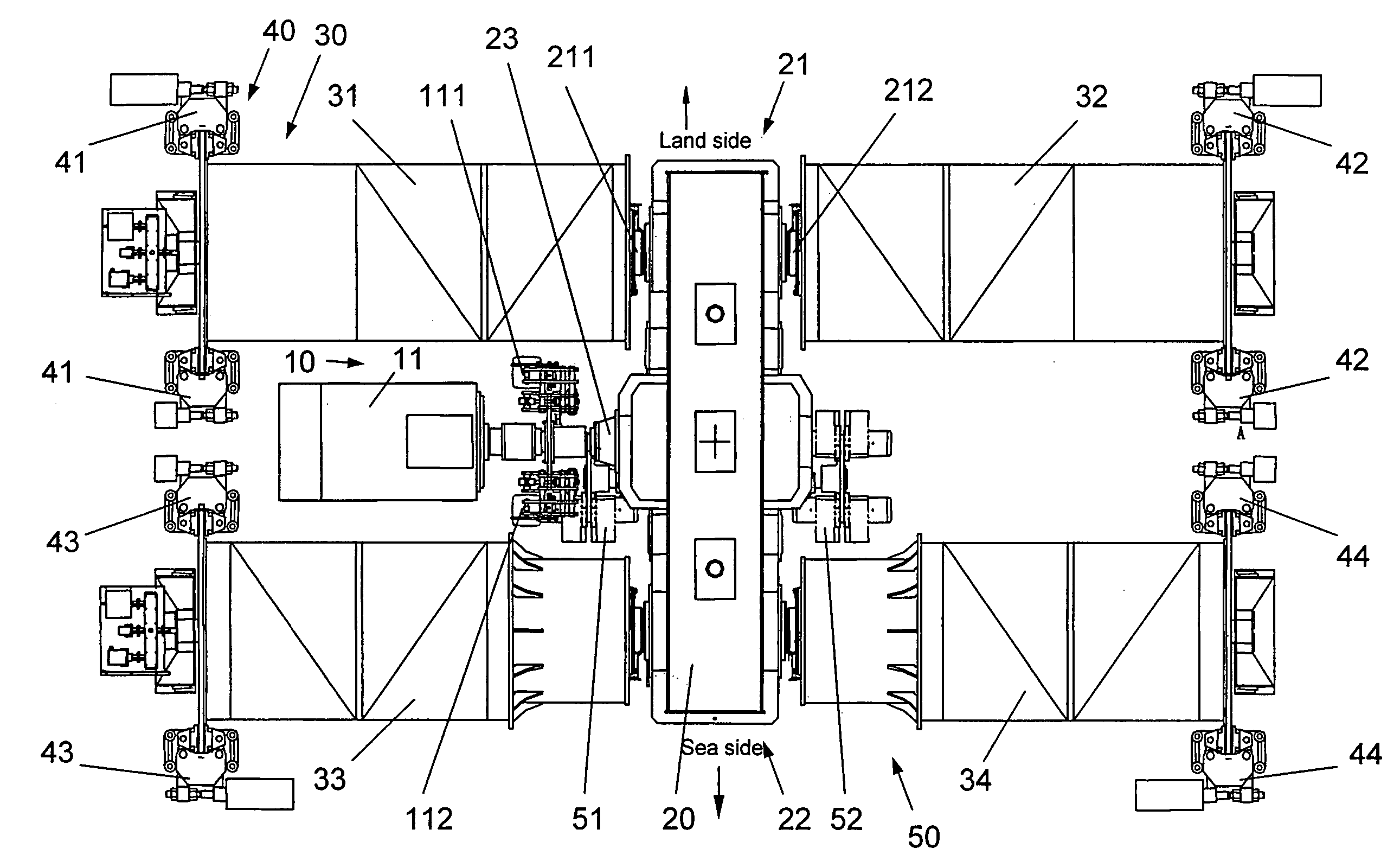
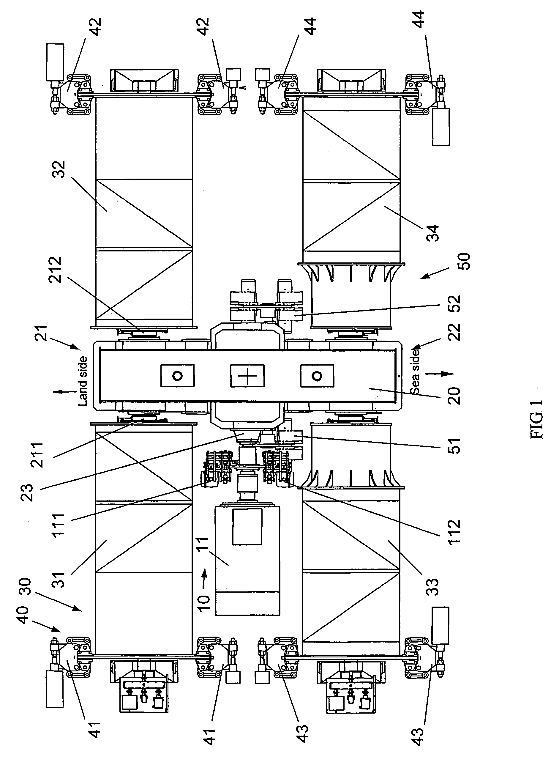
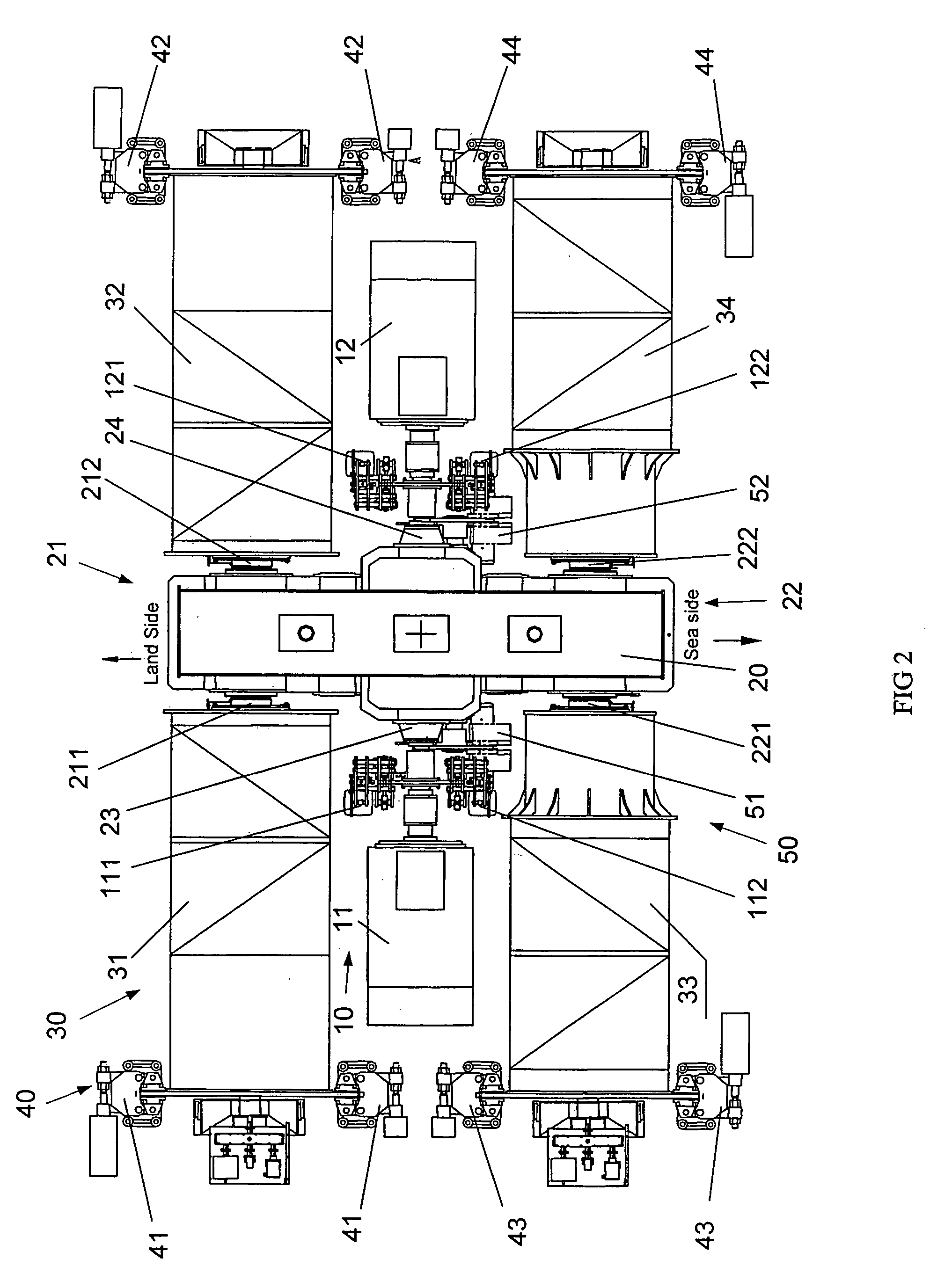
[0020] Referring to FIGS. 1, and 2, they are the schematic structure view of the lifting machinery of four reel differential type for two 40 feet container shore crane according to the invention. The lifting machinery of the invention includes: motor(s) 10, reductor(s) 20 connecting to the motor 10, high speed brake(s) 11 provided on the input end of the reductor 20, a plurality of two-project rope reels 30 connecting to the output end of the reductor 20, a plurality of reel brakes 40 provided on each two-project rope reel 30, and differential shaft brake(s) 50 connecting to the reductor 20, the differential shaft brake(s) 50 control the power distribution of the reductor 20.

[0021] One or two motors may be provided according to the power of the motors; according to the invention, a planetary differential reductor is used as the reductor 20 provided at the output end of the motor 10, the planetary differential reductor 20 has a plurality of high speed input shaft, a plurality of low...


PUM


Abstract

The invention relates to a lifting machinery of four reel differential type for two 40 feet container shore crane comprising: motors, reductors, high speed brakes, reels and reel brakes; wherein at least one motor is provided; the reductor connected at the motor output end is a planetary differential reductor having a plurality of high speed input shafts, low speed output shafts and the differential project shafts; the high speed input shaft connects to the motor output shaft, at least one high speed brake is provided on the high speed input shaft; four two-project rope reels are connected to the four low speed output shaft; at least one reel brake is provided to each reel; and a differential shaft brake consisting of at least two differential shaft brakes provided on two differential project shaft is also included; the revolution of the two differential project shaft of the planetary differential reductor is controlled by the two differential shaft brakes so that power of the planetary differential reductor may be distributed, and both the synchronous operation of two hanger tool or the separate operation of a single hanger tool can be carried out. The present invention meets the loading and unloading requirement and increases the loading and unloading efficiency of the container crane by more than 60%.

Description

FIELD OF INVENTION [0001] The invention generally relates to a lifting machinery for crane, more particularly, relates to a lifting machinery of two reel differential type for two 40 feet container shore crane. BACKGROUND OF INVENTION [0002] The increasing requirements of container transportation in the world and the continuous increment of the handling capacity of the container port put forward new and increased demands on the technical equipment for loading and unloading containers, and an urgent need for the design and development of high efficient bank-run container load and unload systems to meet the demand of the lifter productivity needed by the larger ships. [0003] The main lifting machinery of the crane of the prior art carries out the lifting and lowering operation of one hanger tool only, hence only one 40 feet container or two 20 feet containers can be lifted at a time so that limits the production efficiency and does not meet the market requirement. SUMMARY OF INVENTION...

Claims


Application Information

Patent Timeline
Patent Type & Authority Applications(United States)
IPC IPC(8): F16H37/08
CPCB66D1/22B66D5/14B66D5/00B66D1/26B66C1/12B66C17/20
Inventor SHAN, JIANGUOZHANG, BAOHUA
Owner SHANGHAI ZHENHUA HEAVY IND
Why Eureka
Try Eureka