
Apparatus and method for treatment of damaged tissue

a technology of damaged tissue and apparatus, applied in the field of ultrasonic vibration, can solve the problems of vibration affecting the cleaning of objects, the principle of not being used in the medical field in the cleaning of damaged tissue, etc., and achieve the effect of facilitating debris removal

Inactive Publication Date: 2006-10-26
HEALFUS
View PDF13 Cites 40 Cited by
  • Summary
  • Abstract
  • Description
  • Claims
  • Application Information

AI Technical Summary

Benefits of technology

[0010] Optionally, an interface is provided at the ultrasonic power input to the volume of liquid in the housing. The interface preferably has acoustic properties that are similar to those of the liquid. If the transducer were used to inject the acoustic energy directly into the liquid, the interface between the transducer and the liquid would act as a focus for cavitation, resulting in a marked reduction in the acoustic energy that reaches the skin surface, reducing or eliminating cavitation there. This allows for a higher percentage of generated ultrasound energy to be inserted into the liquid, so that desired cavitation at the tissue surface is generated.
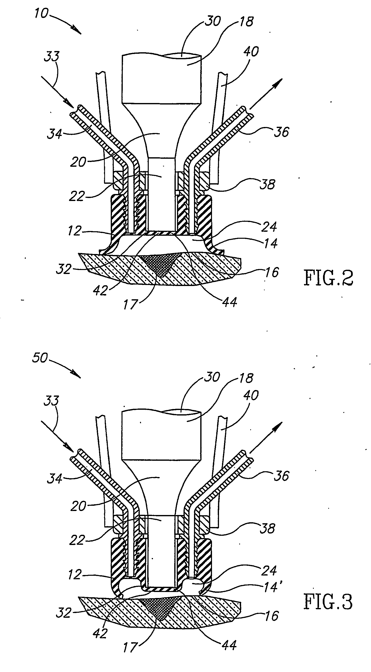
[0013] In an embodiment of the invention, at least a part of the walls of the cavity are elastic. This allows for changing the shape of the cavity so that the input of the ultrasound can be brought closer to and, in some cases, made to touch the skin. In addition, the soft edge is less likely to irritate or damage the wound.
[0015] In an embodiment of the invention, the housing is provided with an inlet for liquid and an outlet for liquid. During operation, as debris is removed, liquid in the housing is replaced, optionally continuously, with the removed debris. Placement of the inlet and outlet induces the removal of the debris from the liquid in the housing. Optionally, the inlet and outlet are placed on opposite sides of the area of the skin being treated, so that the liquid flows across the area, facilitating debris removal from the site of the wound.
[0040] In an embodiment of the invention, activation of the source causes the source to produce sufficient energy to cause cavitation at the patient surface.

Problems solved by technology

The ultrasonic waves cause vibrations which affect cleaning of the objects.
This principle has not, however, been utilized in the medical field in the cleaning of damaged tissue.

Method used


Image

  • Apparatus and method for treatment of damaged tissue
  • Apparatus and method for treatment of damaged tissue
  • Apparatus and method for treatment of damaged tissue

Examples


Embodiment Construction

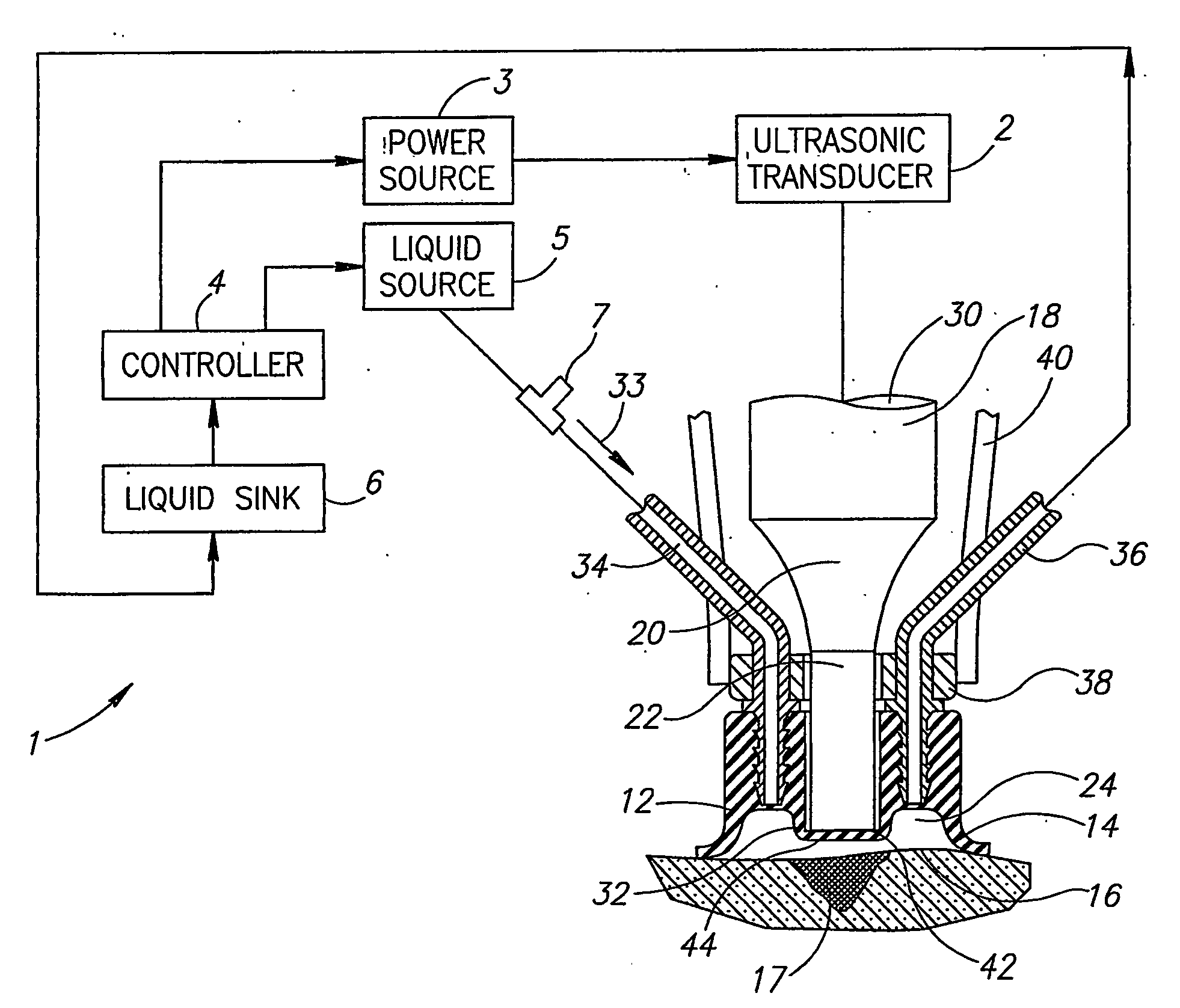
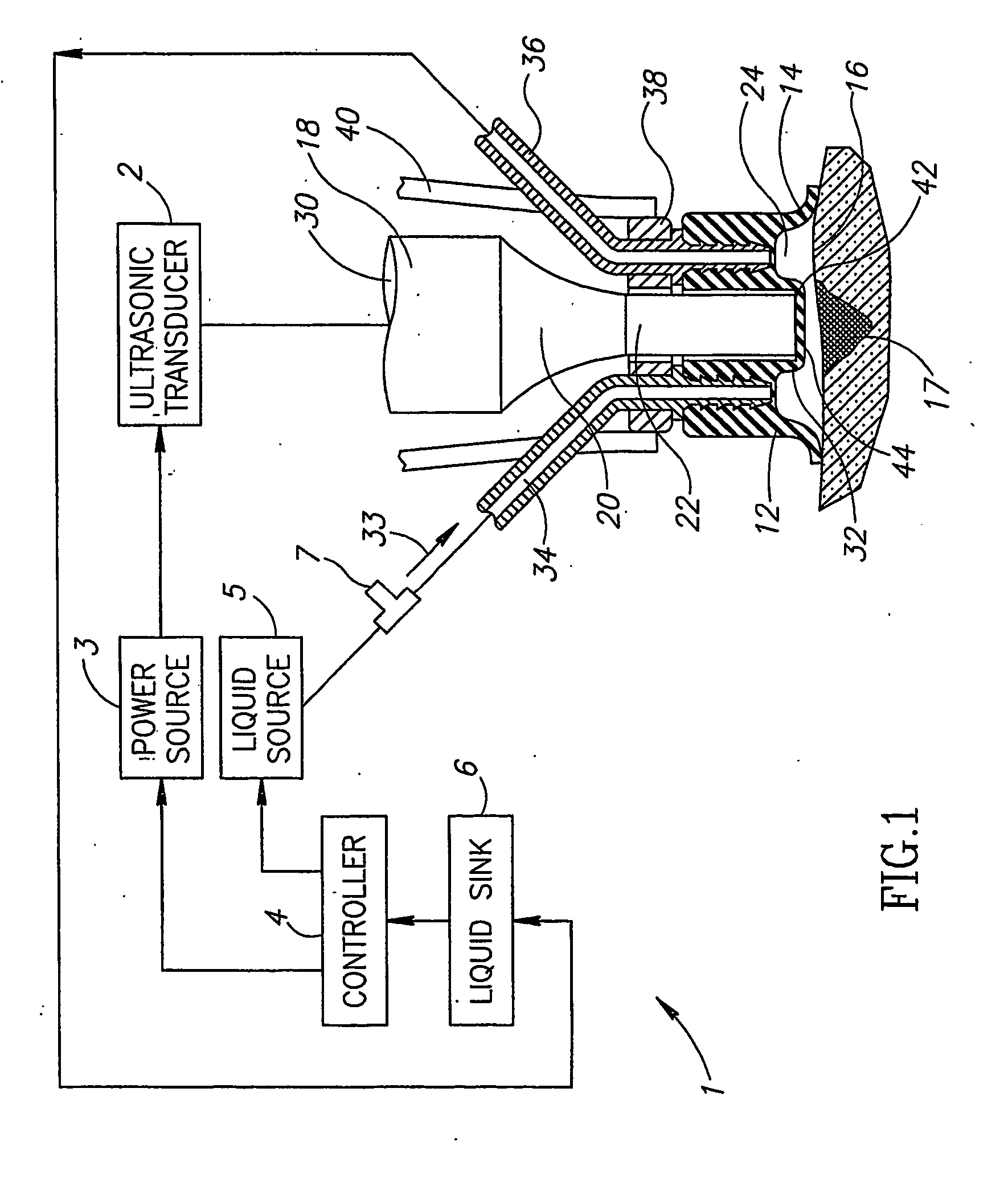
[0048]FIG. 1 illustrates an ultrasonic system 1, for treatment of tissue, in accordance with an exemplary embodiment of the invention. System 1 comprises an ultrasonic treatment device 10 (or 50), described in more detail below, a transducer 2, a source of power 3, a controller 4, a source of liquid 5 and a sink for liquid 6. Optionally, an input 7 for a therapeutic agent is also provided.

[0049] In operation, according to an exemplary embodiment of the invention, device 10 is placed on a skin surface 16 and liquid is supplied to device 10 until all air is removed from a cavity therein, formed between the device and the skin, as described below. Then, the transducer is activated preferably to cause cavitation in the liquid.

[0050]FIGS. 2 and 3 illustrate, in cross-section, ultrasonic devices 10 and 50 for the treatment of damaged tissue, according to embodiments of the present invention. Devices 10 and 50 include an optionally annular housing 12 having a sealing edge, such as the ou...


PUM


Abstract

Apparatus for the ultrasonic treatment of tissue, including: a housing having a space therewithin and an opening adapted for placement against the tissue, the housing being adapted for introducing liquid therein such that when so placed, the space is filled with liquid; and an ultrasonic power source that introduces ultrasonic vibrations toward the damaged tissue, said vibrations having a frequency and power level sufficient to produce cavitation of the liquid at or near the surface of the tissue.

Description

FIELD OF THE INVENTION [0001] The present invention relates to the use of ultrasonic vibrations for skin treatments, for example to cleaning or treatment of damaged tissue. BACKGROUND OF THE INVENTION [0002] It is known in the art to utilize ultrasonic vibrations for the cleaning of various objects, such as machine parts, ball bearings, and surgical instruments. The objects to be cleaned are placed in a liquid, e.g., a detergent solution or a solvent, into which ultrasonic waves are introduced. The ultrasonic waves cause vibrations which affect cleaning of the objects. [0003] It is also known in the medical field to employ ultrasonic vibrations to remove dead tissue and debris from the skin of a person. U.S. Pat. No. 5,656,015, the disclosure of which is incorporated by reference, is concerned with an ultrasonic system comprising a plurality of piezoelectric transducers which are applied to an area of skin to be treated. The affected area can thus be excited from different aspects, ...

Claims


Application Information

Patent Timeline
Patent Type & Authority Applications(United States)
IPC IPC(8): A61H1/00A61B17/00A61B17/22A61H5/00A61N
CPCA61B17/22012A61B2017/00747A61N2007/0039A61B2017/22008A61N2007/0017A61B2017/00761
Inventor GELLER, BENJAMIN
Owner HEALFUS
Learn More