
Aircraft spray booth

Inactive Publication Date: 2006-11-02
GLOBAL FINISHING SOLUTIONS
View PDF12 Cites 11 Cited by
  • Summary
  • Abstract
  • Description
  • Claims
  • Application Information

AI Technical Summary

Benefits of technology

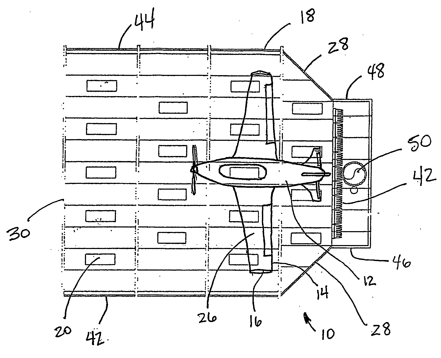
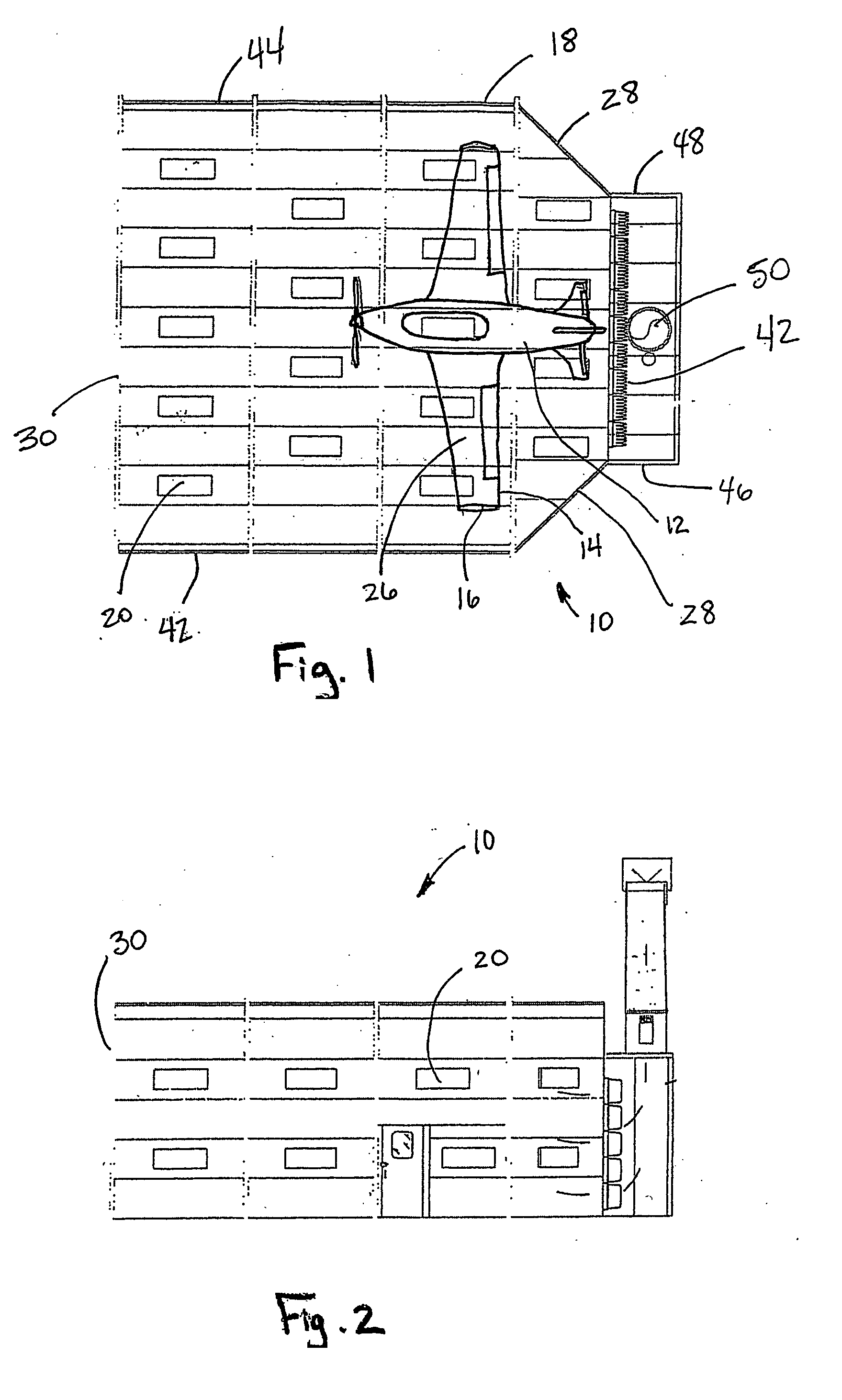
[0005] The disclosed aircraft spray booth provides for effective removal of particulate matter, overspray and volatile organic compounds from the spray booth area without premature and uneven clogging of the filtration system. The aircraft spray booth is designed to create an accelerated airflow within the plenum of the booth to prevent or minimize stratification of the air and reduce particulate matter fallout. The airflow through the booth is increased by the reduction of the filter area to approximately the width of the aircraft fuselage, which is typically ⅓ of the booth width. To compensate for the lack of filtration on the sides of the reduction area, the booth is tapered at the reduction area to cause acceleration of the air at the sidewalls. The acceleration of air at the sidewalls causes a purging of air along the sidewalls and prevents paint and other particulate matter from adhering to the sidewalls.
[0006] The aircraft spray booth may be used with dry filter banks from 1 to 3 stages, water wash air cleaning and with carbon adsorption filter cells. The aircraft spray booth may also be used with draw-through and forced air style air intakes. Since the walls of the spray booth are closer to the fuselage of the aircraft, lighting can be placed closer to the painted surface in the tail section of the aircraft to aid in the accuracy of the painting process.

Problems solved by technology

Prior art spray booths are adequate for spraying automobiles but are inadequate for spraying aircraft since premature filter clogging occurs on the filters near the center of the filter banks since the majority of the paintwork occurs near the centerline of the booth.

Method used


Image

  • Aircraft spray booth
  • Aircraft spray booth
  • Aircraft spray booth

Examples


Embodiment Construction

[0014] For the purpose of promoting an understanding of the principles of the invention, references will be made to the embodiments illustrated in the drawings. Specific language will also be used to describe the same. It will, nevertheless, be understood that no limitation of the scope of the invention is thereby intended, such alterations and further modifications in the illustrated device, and such further applications of the principles of the invention illustrated herein being contemplated as would normally occur to one skilled in the art to which the invention relates.

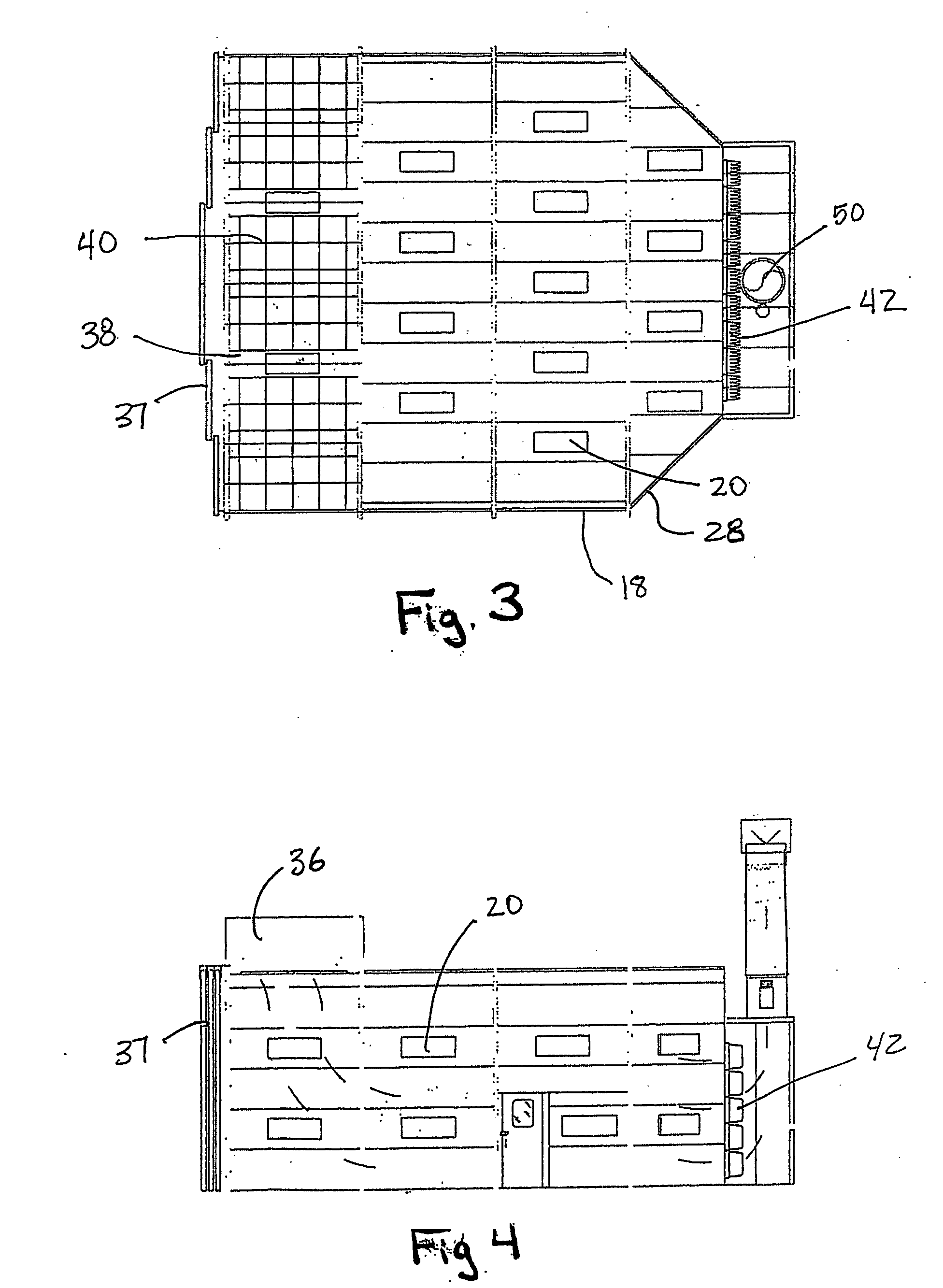
[0015] The present invention is directed to a cross draft spray booth 10 for aircraft 12 that has advanced airflow characteristics to allow for the enhanced capture of contaminants associated with painting aircraft. Airflow through the aircraft spray booth is enhanced by the dimensional layout of the booth. The cross sectional area of the spray booth is not a constant dimension, but varies, tapering near the rear...


PUM

PropertyMeasurementUnit
Volumeaaaaaaaaaa
Accelerationaaaaaaaaaa
Widthaaaaaaaaaa

Abstract

The invention is directed to an aircraft spray booth providing for effective removal of particulate matter, overspray and volatile organic compounds from the spray booth area without premature and uneven clogging of the filtration system. The present invention is designed to create an accelerated airflow within the plenum of the spray booth to prevent or minimize stratification of the air and reduce particulate matter fallout. The airflow through the booth is increased by the reduction of the spray booth and filter area to approximately ⅓ of the original booth width. The decrease in the cross sectional area of the spray booth increases the overall speed of the airflow and decrease the volume of air exchanged through the booth. The spray booth is tapered at the reduction area to cause acceleration of the air at the sidewalls. The acceleration of air at the sidewalls causes a purging of air along the sidewalls and prevents paint and other particulate matter from adhering to the sidewalls. The reduction in the spray booth allows lighting can be placed closer to the painted surface in the tail and fuselage section of the aircraft to aid in the accuracy of the painting process.

Description

[0001] This application claims the benefit of U.S. Provisional Application No. 60 / 438,428 filed Jan. 6, 2003.BACKGROUND OF THE INVENTION [0002] The present invention relates to spray booths that are used to enclose dangerous activities, such as painting and stripping, that are performed therein, and to contain the risk of fire. Spray booths are also used to control the overspray from spray paint guns and capture the paint particles that are not applied to the object being painted. Spray booths are designed in accordance with local and national electrical and fire codes' and are typically fabricated in a single or double wall construction. [0003] Spray booths typically include a filter section that is comprised of a set of filter racks, a plenum and a set of filters. Airflow created by a fan places the plenum under negative pressure. The fan ejects the cleaned air to the atmosphere. Airflow through a spray booth is an important design consideration. Desired airflow through the spray ...

Claims


Application Information

Patent Timeline
IPC IPC(8): B05B15/12B01D46/00
CPCB01D46/0036B05B15/1222B05B15/12B01D46/28B05B16/00B05B16/60
Inventor THELEN, RICHARD L.
Owner GLOBAL FINISHING SOLUTIONS
Learn More