Energy absorbing airframe for a vertical lift vehicle

a vertical lift vehicle and airframe technology, applied in the field of airframes, can solve the problems of difficult prediction, low efficiency of landing gear, and high mass, and achieve the effect of minimizing the likelihood that the rotor blades may penetrate the crew compartment and minimizing the potential

Active Publication Date: 2006-11-02
SIKORSKY AIRCRAFT CORP
View PDF16 Cites 17 Cited by
  • Summary
  • Abstract
  • Description
  • Claims
  • Application Information

AI Technical Summary

Benefits of technology

[0009] In response to reaching the predetermined threshold load value during a high sink rate impact event, the collapsible member will collapse under the aft section of the upper deck and the rotational joint will operate as a virtual hinge such that a forward section of the upper deck deforms in a predictable manner to form the rotational joint. As the upper deck supports the high mass systems, the high mass components will move with the upper deck in a controlled manner during the impact event. As the collapsible members collapse, the high mass components are less likely t...

Problems solved by technology

While the landing gear is a primary element in attenuating energy in impacts, there are conditions when the landing gear may be rendered ineffective, such as water landings, rough terrain, and when the gear is retracted.
Failure modes such as buckling, tearing, crippling, stretching, shearing all absorb energy, but these modes may be relatively inefficient, and difficult to predict.
One particular complexity with a helicopter is that high mass systems such as engines, transmissions, main rotor systems, etc. are typically located above the crew and passenger compartments.
Deceleration forces during an impact event may cause the high mass systems to sepa...

Method used


Image

  • Energy absorbing airframe for a vertical lift vehicle
  • Energy absorbing airframe for a vertical lift vehicle
  • Energy absorbing airframe for a vertical lift vehicle

Examples


Embodiment Construction

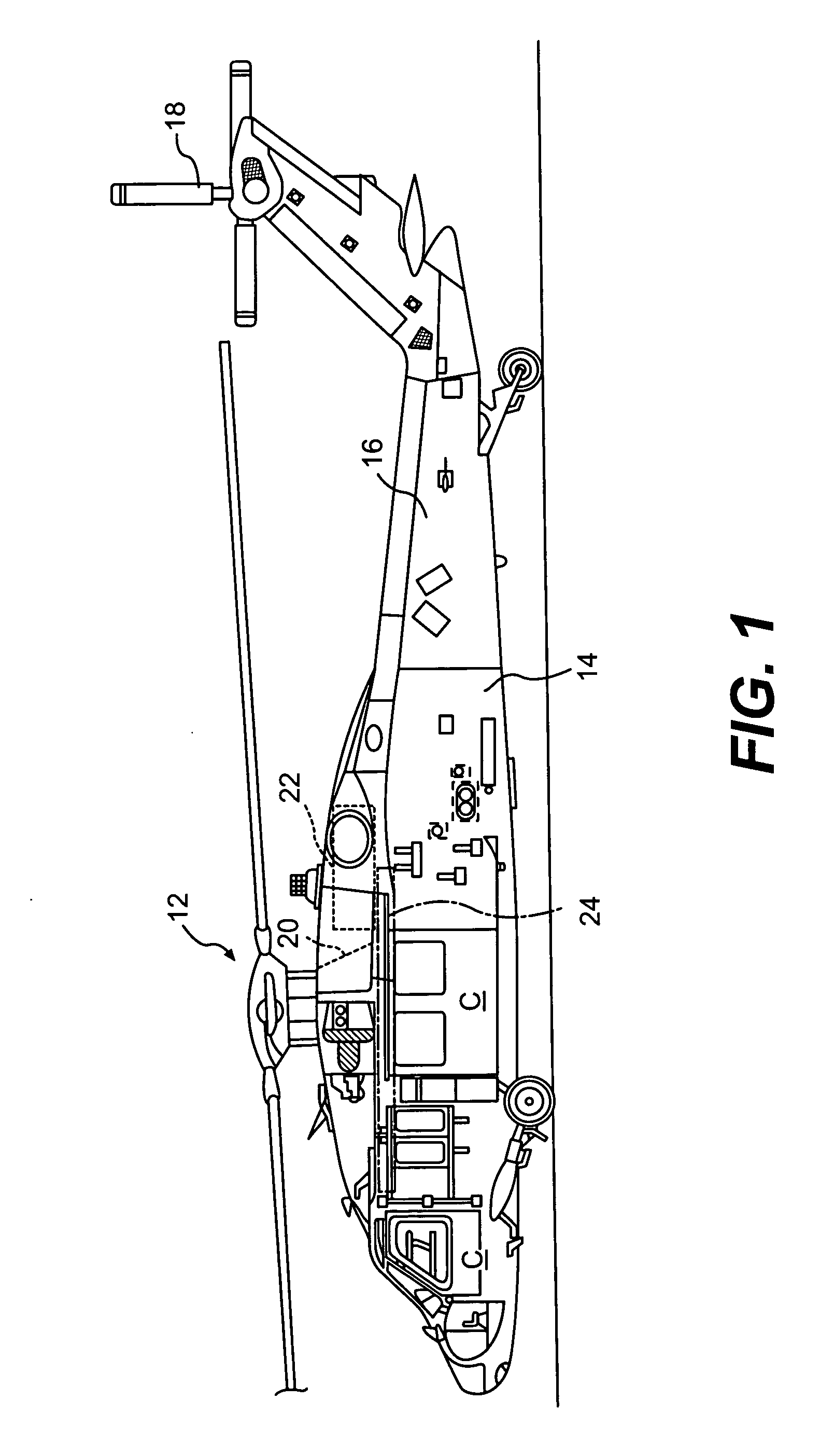
[0025]FIG. 1 schematically illustrates a rotary-wing aircraft 10 having a main rotor assembly 12. The aircraft 10 includes an airframe 14 having an extending tail 16 which mounts an anti-torque rotor 18. The main rotor assembly 12 is driven through a transmission (illustrated schematically at 20) by one or more engines 22.

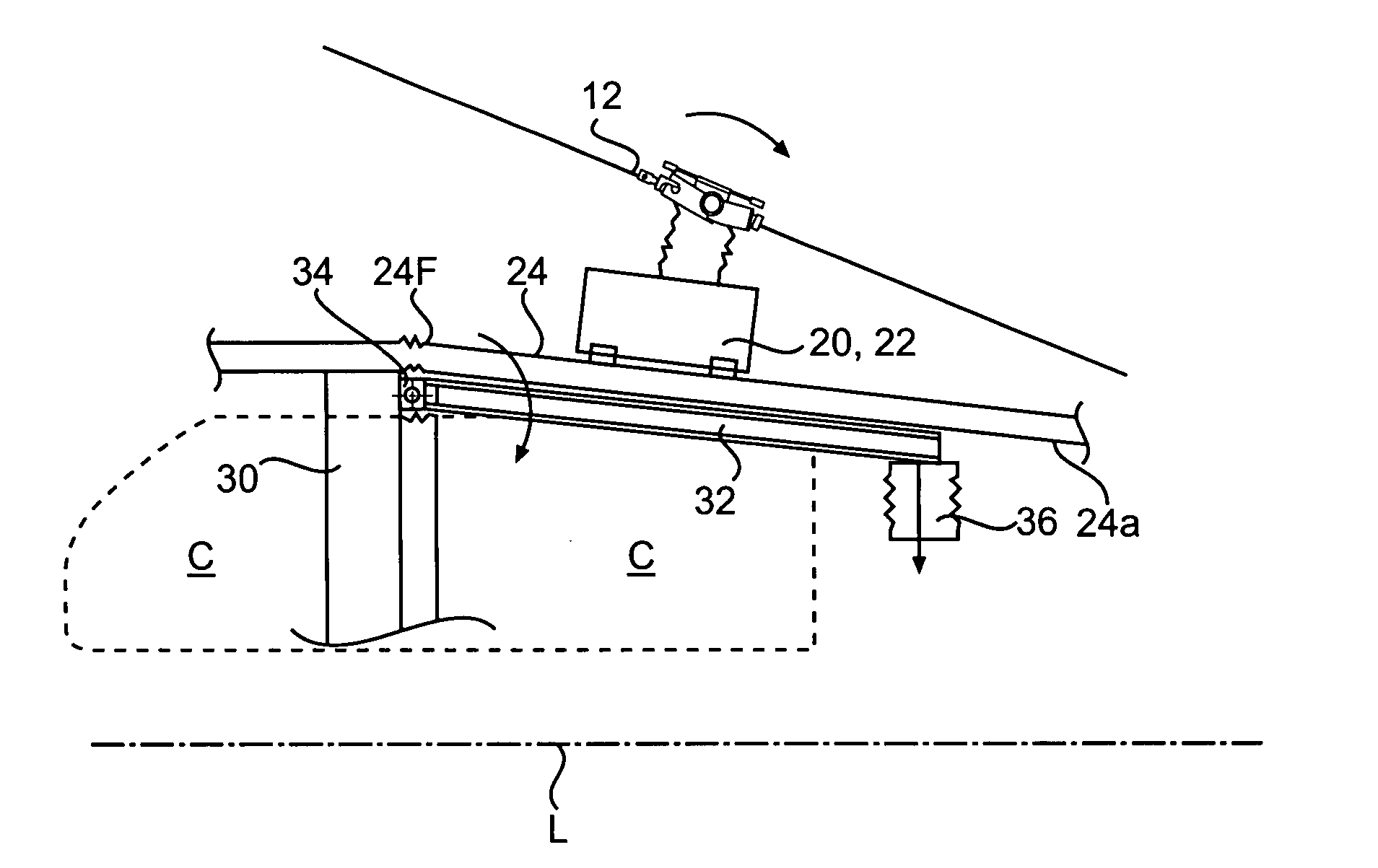
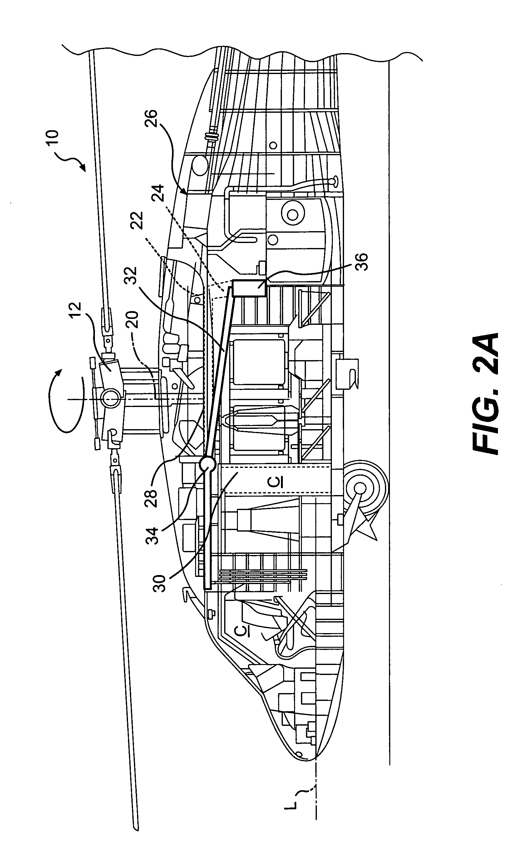
[0026] The main rotor assembly 12, transmission 20 and the engines 22 are high mass systems mounted to an upper deck 24 (FIG. 2A) at mount locations 25 (FIG. 2B) which is located generally above a crew compartment C. It should be understood that “crew component” as utilized herein refers to both the cockpit and the passenger cabin but primarily to the cockpit. It should be understood that the term “upper deck’ as utilized herein may include a multiple of airframe structures which at least partially provide support the high mass components and which is located at least partially above the crew compartment C. Although a particular helicopter configuration is illustr...


PUM


Abstract

An airframe includes an energy absorbing structure with a frame, a beam mounted to the frame at a rotational joint and a collapsible member. In response to reaching a predetermined threshold load value during a high sink rate impact event, the collapsible member will collapse under an aft section of the upper deck. The rotational joint operates as a virtual hinge such that a forward section of the upper deck deforms in a predictable manner. As the upper deck supports the high mass systems, the high mass components are less likely to separate from their mounting and penetrate into the crew compartment and the main rotor system will tilt aft away from the crew compartment to minimize the likelihood that the rotor blades may penetrate the crew compartment.

Description

[0001] This invention was made with government support under Contract No.: DAAH10-03-02-0003 awarded by the Department of the Army. The government therefore has certain rights in this invention.BACKGROUND OF THE INVENTION [0002] The present invention relates to an airframe, and more particularly to an airframe structure which attenuates energy during a high sink rate impact event and minimizes the potential that high mass components may enter the crew compartment. [0003] In order to survive high sink rate impacts, helicopters typically utilize a combination of landing gear, fuselage crushing and seat stroking to attenuate energy. While the landing gear is a primary element in attenuating energy in impacts, there are conditions when the landing gear may be rendered ineffective, such as water landings, rough terrain, and when the gear is retracted. In these scenarios, the aircraft fuselage is the primary energy attenuation structure. [0004] The fuselage attenuates energy through vario...

Claims


Application Information

Patent Timeline
IPC IPC(8): B64C27/00
CPCB64C27/006B64C1/062
Inventor TOWNSEND, WILLIAMKAY, BRUCE FREDRIC
Owner SIKORSKY AIRCRAFT CORP
Why Eureka
Try Eureka