Valve seat edge relief profile

a valve seat and edge relief technology, applied in the field of gate and ball valve seats, can solve the problems of high bearing load on increase the friction between the gate and the seat ring, and galling or marring the surface finish of the gate-seat interface, so as to reduce the axial stiffness of the valve seat, and improve the non-uniform bearing stress distribution

Active Publication Date: 2006-11-02
VETCO GRAY LLC
View PDF8 Cites 2 Cited by
  • Summary
  • Abstract
  • Description
  • Claims
  • Application Information

AI Technical Summary

Benefits of technology

[0007] The present invention significantly improves this non-uniform bearing stress distribution by reducing the axial stiffness of the valve seat in the areas of highest bearing stress, which is at the inner and outer edges of the seat face. This reduction in axial stiffness is accomplished by creating a semi-flexible flange at these edges. Hence under load, the flanges flex. Thereby creating a bearing stress profile across the seat face that is much more uniform.
[0008] The valve seat of this invention comprises a tubular member having an exterior surface, a rearward end, a face, a forward end and a passage extending from the rearward end to the face. A radially extending annular inner diameter flange is located at the inner diameter of the face. The flange has a forward side that defines an inner periphery of the passage. The flange has a rearward side that faces in the rearward direction. The flange flexes slightly under load to reduce contact stress at the inner periphery of the face.

Problems solved by technology

In some cases, these gate valves are subject to high bearing loads due to high pressure forcing the gate against the seat ring.
Moving the gate under high loads may lead to galling or marring the surface finish of the gate-seat interface.
Galling increases the friction between the gate and seat ring and reduces the sealability.
Premature failure may result.
All materials in normal bearing contact will experience failure or damage to the surface finishes if loaded to a high enough level when subject to dynamic motion.
It is also well established that lubricants, such as grease, have diminished capacity to provide lubrication as the bearing stress becomes extreme.
This is because the surface tension and viscosity of the fluid are unable to support the high loads resulting in surface contact and subsequent surface damage.

Method used


Image

  • Valve seat edge relief profile
  • Valve seat edge relief profile
  • Valve seat edge relief profile

Examples


Embodiment Construction

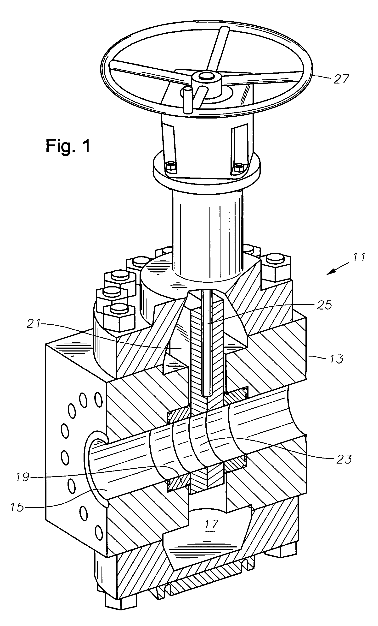
[0016] Referring to FIG. 1, gate valve 11 has a body 13. Body 13 has two co-axial passages 15 (only one shown) that extend to a central cavity 17 from opposite sides of body 13. Passages 15 connect to a flowline or other mating equipment (not shown). A seat ring 19 (only one shown) is mounted in each passage 15. Each seat ring 19 locates at the junction of one of the passages 15 with cavity 17 and protrudes into cavity 17.

[0017] A gate member 21 moves within cavity 17 between an open position, which is shown, and a closed position. Gate 21 may be a split slab or may be a single slab as shown. Gate 21 has a hole 23 through it that registers with passages 15 when in the open position. A stem 25 causes gate 21 to move between the open and closed positions. Stem 25 may be either a non-rising type or a type that moves along its axis when rotated. Gate 21 may be actuated hydraulically, electrically, or by a hand wheel 27, as shown.

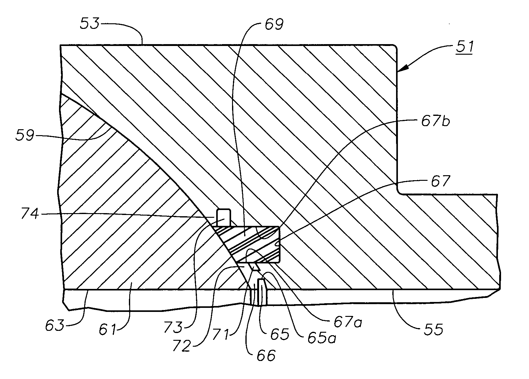
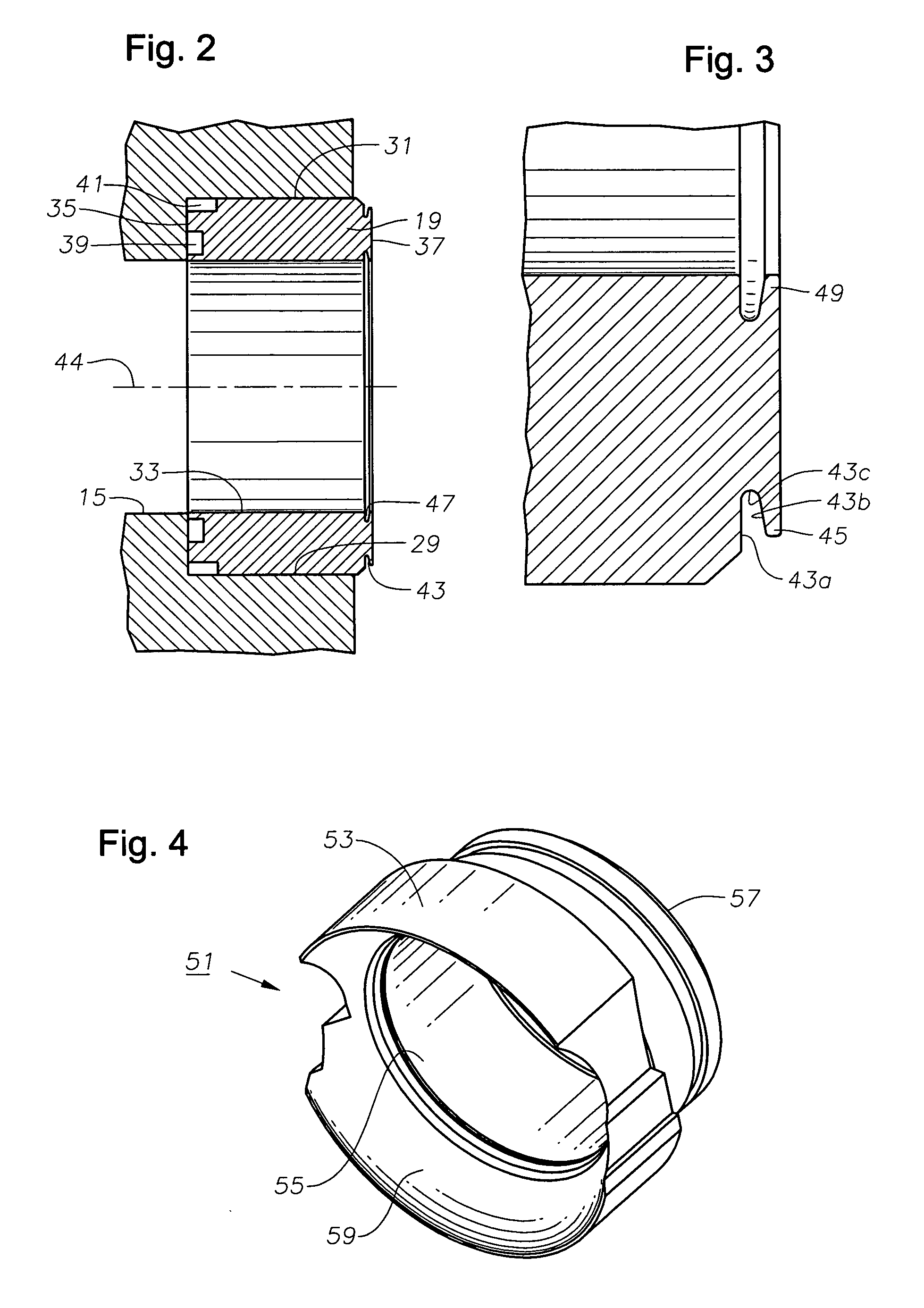
[0018] Referring to FIG. 2, seat ring 19 is located with...


PUM


Abstract

A valve seat has an outer surface, a rearward end, a face and a forward end. A passage extends from the rearward end to the face. A valve element slidingly contacts the face. Stress relief flanges are located on the face in areas of high bearing stress. Each flange has a thickness that allows it to deflect slightly to reduce bearing stresses.

Description

FIELD OF THE INVENTION [0001] This invention relates in general to gate and ball valve seats, and in particular to a profile formed on the seat for relieving bearing stress. BACKGROUND OF THE INVENTION [0002] A gate valve has a body with a central cavity that is intersected by two coaxial passages. Seat rings are located at the intersections of each passage with the cavity. Each seat ring has a face that is engaged by a gate that moves between an open and a closed position. In some cases, these gate valves are subject to high bearing loads due to high pressure forcing the gate against the seat ring. Moving the gate under high loads may lead to galling or marring the surface finish of the gate-seat interface. Galling increases the friction between the gate and seat ring and reduces the sealability. Premature failure may result. [0003] A ball valve also utilizes a seat ring with a face that slidingly engages a sealing element, which in this case is a ball element. The face of the seat...

Claims


Application Information

Patent Timeline
Patent Type & Authority Applications(United States)
IPC IPC(8): F16K1/42
CPCF16K3/0227F16K25/00F16K5/0673F16K5/0663F16K25/04F16K3/02F16K5/06
Inventor HUNTER, RICK C.
Owner VETCO GRAY LLC
Why Eureka
Try Eureka