Passive polyphase filter

a polyphase filter and polyphase technology, applied in the field can solve the problems of complex configuration and complicated layout of passive polyphase filters, and achieve the effects of suppressing the complication of layout and wiring, reducing the influence of characteristics, and simple component layout and wiring shap

Inactive Publication Date: 2006-11-02
COLLABO INNOVATIONS INC
View PDF2 Cites 8 Cited by
  • Summary
  • Abstract
  • Description
  • Claims
  • Application Information

AI Technical Summary

Benefits of technology

[0012] Therefore, with the foregoing in mind, it is an object of the present invention to provide a passive polyphase filter having a simple component layout and wiring shape, so that a complication of the layout and the wirings is suppressed even when the passive polyphase filter has a configuration of plural stages, thereby reducing the influence on the characteristics by a parasitic element caused by the layout of the respective components.
[0013] Another object of the present invention is to provide a passive polyphase filter that easily can be equalized in the characteristic influences from the parasitic element due to the layout of the components.

Problems solved by technology

As a result, the layout of the passive polyphase filter becomes complicated.
In addition to that, when the 2-stage 4-phase input passive polyphase filter as shown in FIG. 23 is configured on the basis of the layout manner in FIG. 22, the configuration will be complicated considerably as shown in FIG. 25.

Method used


Image

  • Passive polyphase filter
  • Passive polyphase filter
  • Passive polyphase filter

Examples


first embodiment

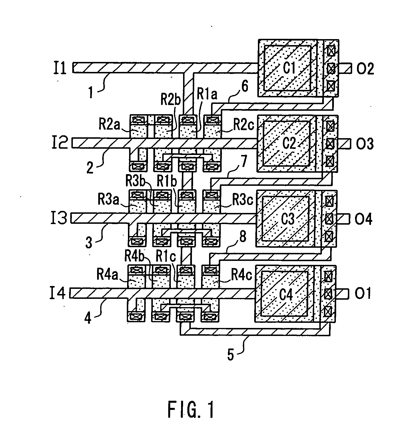
[0053]FIG. 1 is a plan view showing a layout of a passive polyphase filter according to a first embodiment. This layout configures a 4-phase input passive polyphase filter having the circuit structure of FIG. 20. In the explanation, components identical to those in the conventional examples as shown in FIGS. 21, 22 or the like will be assigned with the same reference numerals.

[0054] In the layout of FIG. 1, each of the resistors R1-R4 of FIG. 20 is divided into three parts and configured as a group of partial resistors. That is, the resistor R1 is composed of a group of partial resistors R1a-R1c, the resistor R2 is composed of a group of partial resistors R2a-R2c, the resistor R3 is composed of a group of partial resistors R3a-R3c, and the resistor R4 is composed of a group of partial resistors R4a-R4c. As clarified in the following embodiments, in the present invention, each of the resistors of m in number is divided into and configured as partial resistors of at least (m-1) in nu...

second embodiment

[0066]FIG. 6 is a circuit diagram of a 3-phase input passive polyphase filter in a second embodiment. Resistors R1-R3 and capacitors C1-C3 are connected in a loop, to which input nodes I1-I3 and output nodes O1-O3 are provided. FIG. 7 is a plan view showing a layout of the respective components of the 3-phase input passive polyphase filter shown in FIG. 6. The circuit structure and the layout of the respective components are the same substantially as those in the first embodiment, and thus the same reference numerals are assigned to the same components in order to avoid the duplicate explanation.

[0067] Each of the resistors R1-R3 in FIG. 6 is divided into two parts and composed as a group of partial resistors as in FIG. 7. The resistor R1 is composed of a group of partial resistors R1a-R1b, the resistor R2 is composed of a group of partial resistors R2a-R2b, and the resistor R3 is composed of a group of partial resistors R3a-R3b. For the resistors R2-R3, the partial resistors R2a-R...

third embodiment

[0072]FIG. 10 is a circuit diagram of a 5-phase input passive polyphase filter in a third embodiment. Resistors R1-R5 and capacitors C1-C5 are connected in a loop, to which input nodes I1-I5 and output nodes O1-O5 are provided. FIG. 11 is a plan view showing a layout of the respective components of the 5-phase input passive polyphase filter shown in FIG. 10. The circuit structure and a layout of the respective components are substantially the same as those in the first embodiment, and the same reference numerals are assigned to the same components in order to avoid the duplicate explanation.

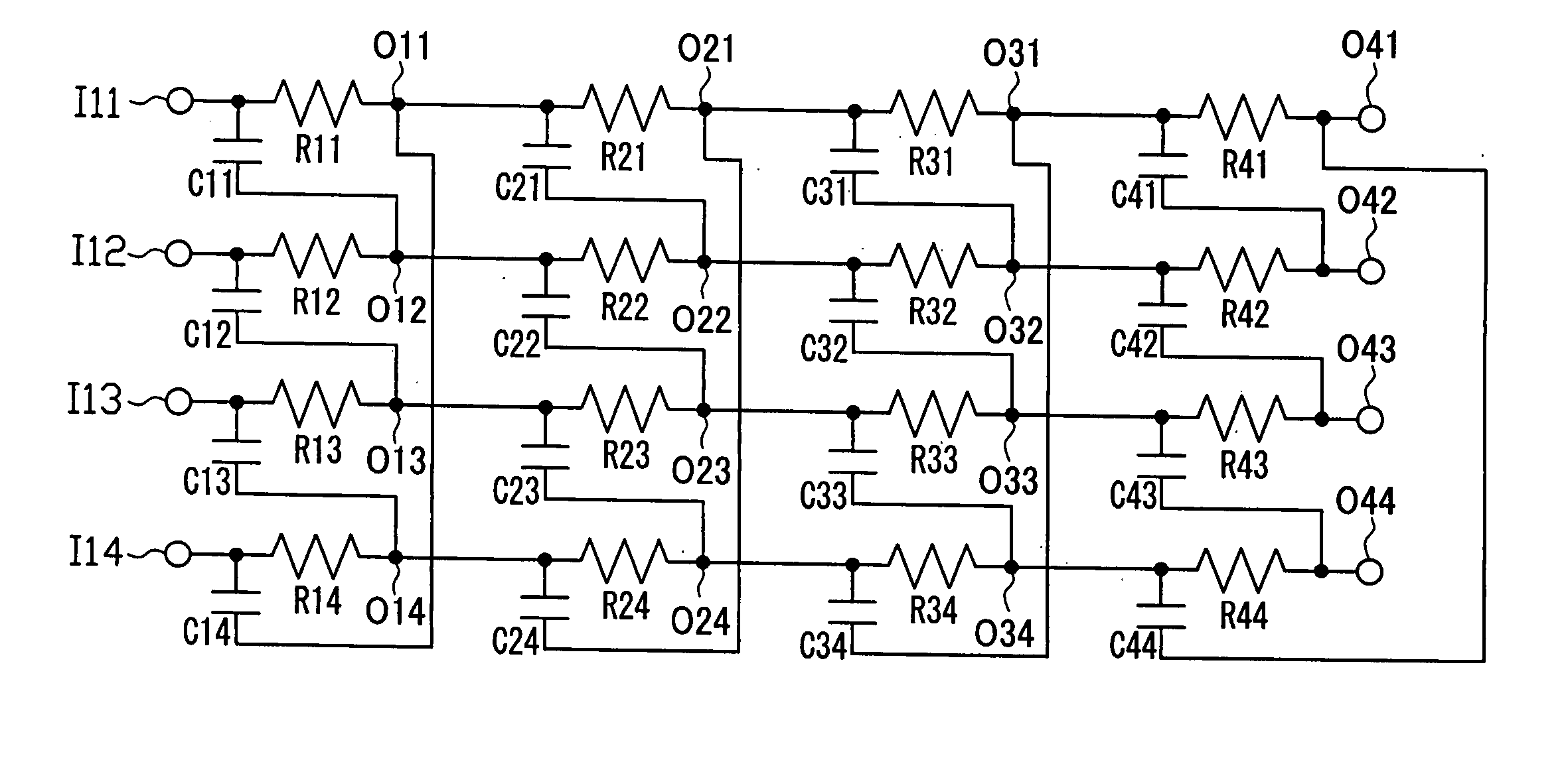
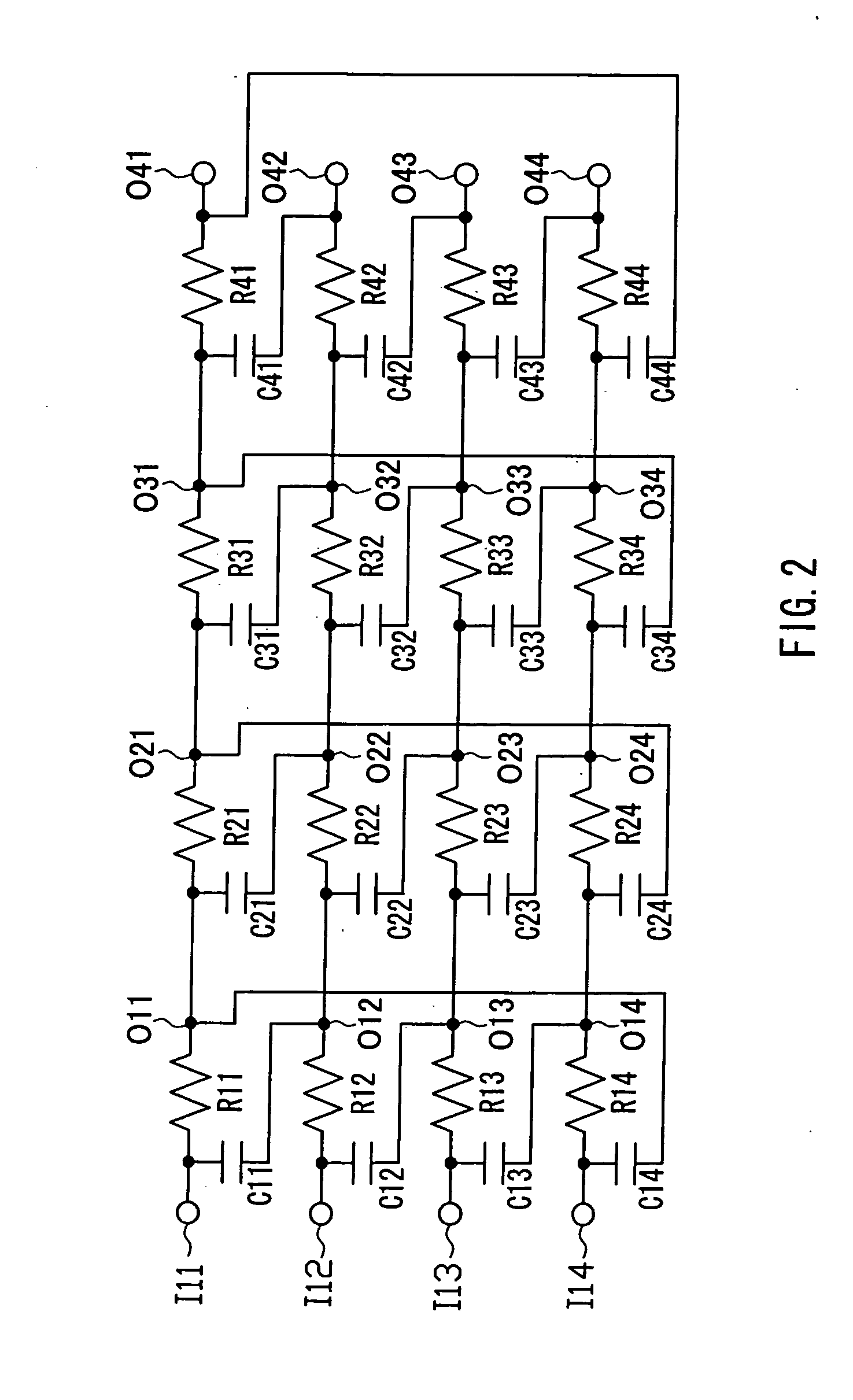
[0073] As an application example of the configuration in this embodiment, FIG. 12 shows a circuit diagram of a 3-stage 5-phase input passive polyphase filter. With respect to a first stage filter including resistors R11-R15 and capacitors C11-C15, a second stage filter including resistors R21-R25 and capacitors C21-C25 is connected at output nodes O11-O15 of the first stage filter. In the same m...


PUM


Abstract

Four input nodes I1-I4 for inputting 4-phase signals, four resistors R1-R4, four capacitors C1-C4, and four output nodes O1-O4 for outputting 4-phase signals are provided. The resistors and the capacitors are connected alternately in a loop, and the input nodes and output nodes are connected alternately to the respective nodes between the resistors and the capacitors sequentially. Each of the four resistors is composed of a group of three or more partial resistors, and three groups of the partial resistors R2a-R2c, R3a-R3c and R4a-R4c are collected respectively and arranged in the same attitude, while the partial resistors R1a-R1c of the remaining group are distributed into the other groups and arranged in the same line the same attitude as the partial resistors of each of the other groups. The regions of the thus collected groups are arranged in one direction. By simplifying the layout of the components and the shape of the wirings, influences on the characteristics by the parasitic elements are reduced, and complication in the layout and wirings can be suppressed even when using plural stages.

Description

BACKGROUND OF THE INVENTION [0001] 1. Field of the Invention [0002] The present invention relates to a passive polyphase filter (complex filter) used for image rejection or the like in signal processing in electronic equipment, and particularly, the present invention relates to the improvement in a layout of components such as resistors, capacitors and input / output nodes. [0003] 2. Description of Related Art [0004] A passive polyphase filter used for image rejection in signal processing in electronic equipment has a circuit structure as shown in FIG. 20 in the case of a 4-phase input, for example. The passive polyphase filter in FIG. 20 is configured by connecting resistors R1, R2, R3, R4 and capacitors Cl, C2, C3, C4 in a loop. I1, I2, I3 and I4 are input nodes through which signals are inputted, and O1, O2, O3 and O4 are output nodes through which signals are outputted. The resistors R1-R4 have the same resistance value, and the capacitors C1-C4 have the same capacitance value. [0...

Claims


Application Information

Patent Timeline
Patent Type & Authority Applications(United States)
IPC IPC(8): H03H7/01
CPCH03H7/21
Inventor OZASA, MASAYUKIYOKOYAMA, AKIOOOKUBO, MANABUSORAMOTO, TAKAO
Owner COLLABO INNOVATIONS INC
Why Eureka
Try Eureka