Controller driver and display apparatus using the same

Active Publication Date: 2006-11-02
RENESAS ELECTRONICS CORP +1
View PDF19 Cites 21 Cited by
  • Summary
  • Abstract
  • Description
  • Claims
  • Application Information

AI Technical Summary

Benefits of technology

[0022] The present invention effectively reduces the image data transmission to controller/drivers, and thereby reduces the power consumption of the controller/drivers while achieving the display of high grayscale images on liquid crystal display

Problems solved by technology

Increase in the number of the graylevels of image data requires the number of data bits of image data for each pixel, and this leads to the increase in the amount of image data.
Additionally, improvement of smoothness of moving pictures requires numbers of frames per unit of time, and this also leads to increase in the amount of image data.
Nevertheless, the increase in the am

Method used


Image

  • Controller driver and display apparatus using the same
  • Controller driver and display apparatus using the same
  • Controller driver and display apparatus using the same

Examples


first modification

[0086] With reference to FIG. 7, it is advantageous that a latch circuit 20 is inserted between the work memory 12 and the display memory 13. The latch circuit 20 receives the pixel data associated with the target line of the image from the work memory 12 and temporary stores therein the received pixel data. The latch circuit 20 effectively reduces the duration necessary for the work memory 12 to output the pixel data of the desired line. This preferably reduces the working duration of the work memory 12. Additionally, the latch circuit 20 preferably eliminates a need for operating the work memory 12 and the display memory 13 at the same time during the transfer of the bitmap data from the work memory 12 to the display memory 13.

second modification

[0087]FIG. 8 illustrates the structure of the controller / driver 1 in a second modification of this embodiment. In this modification, the controller / driver 1 is adapted to drive a pair of LCDs using the work memory 12 and the display memory 13. Other than this exception, the controller / driver 1 in this modification is designed similarly to that shown in FIG. 7.

[0088] One of the LCDs is referred to as a main LCD 32, and the other is referred to as the sub LCD 33. The main LCD 32 includes H data lines 32a and V gate lines 32b. Pixels (not shown) are disposed at the respective intersections of the data and gate lines 32a and 32b. Correspondingly, the sub LCD 33 includes H data lines 33a and V gate lines 33b, and pixels (not shown) are disposed at the respective intersections of the data and gate lines 33a and 33b.

[0089] In order to drive the two LCDs: the main and sub LCDs 32 and 33, the controller / driver 1 includes a pair of gate line drivers 24 and 25. The gate line driver 24 is use...

third modification

[0100] In third and fourth modifications, the controller / driver 1 is adapted to perform various calculations during the transfer of the bitmap data from the work memory 12 to the display memory 13. Providing calculating means for performing calculations on the transferred bitmap data preferably reduces a need for externally performing processing of the bitmap data, including processing by the CPU 2.

[0101] As shown in FIG. 11, the controller / driver 1 in the third modification is comprised of a graylevel converter 26 interposed between the work memory 12 and the display memory 13. The gray level converter 26 allows the number of the data bits of the pixel data stored in the work memory 12 to be different from that stored in the display memory 13.

[0102] The number of the bit lines of the work memory 12 and the display memory 13 are modified in accordance with the numbers of the data bits of the pixel data. When the graylevel of each pixel is represented by n1 bits within the bitmap d...


PUM


Abstract

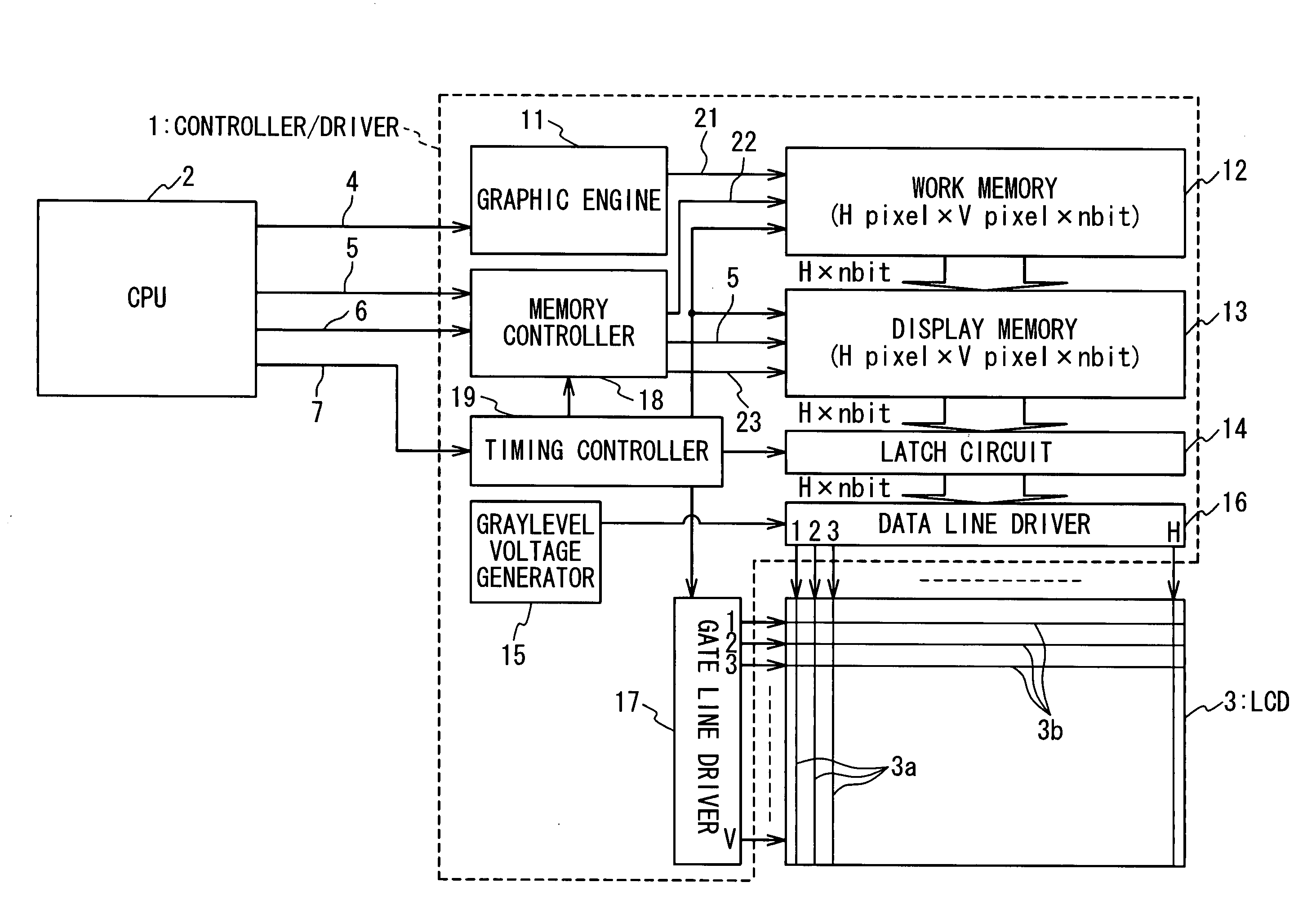
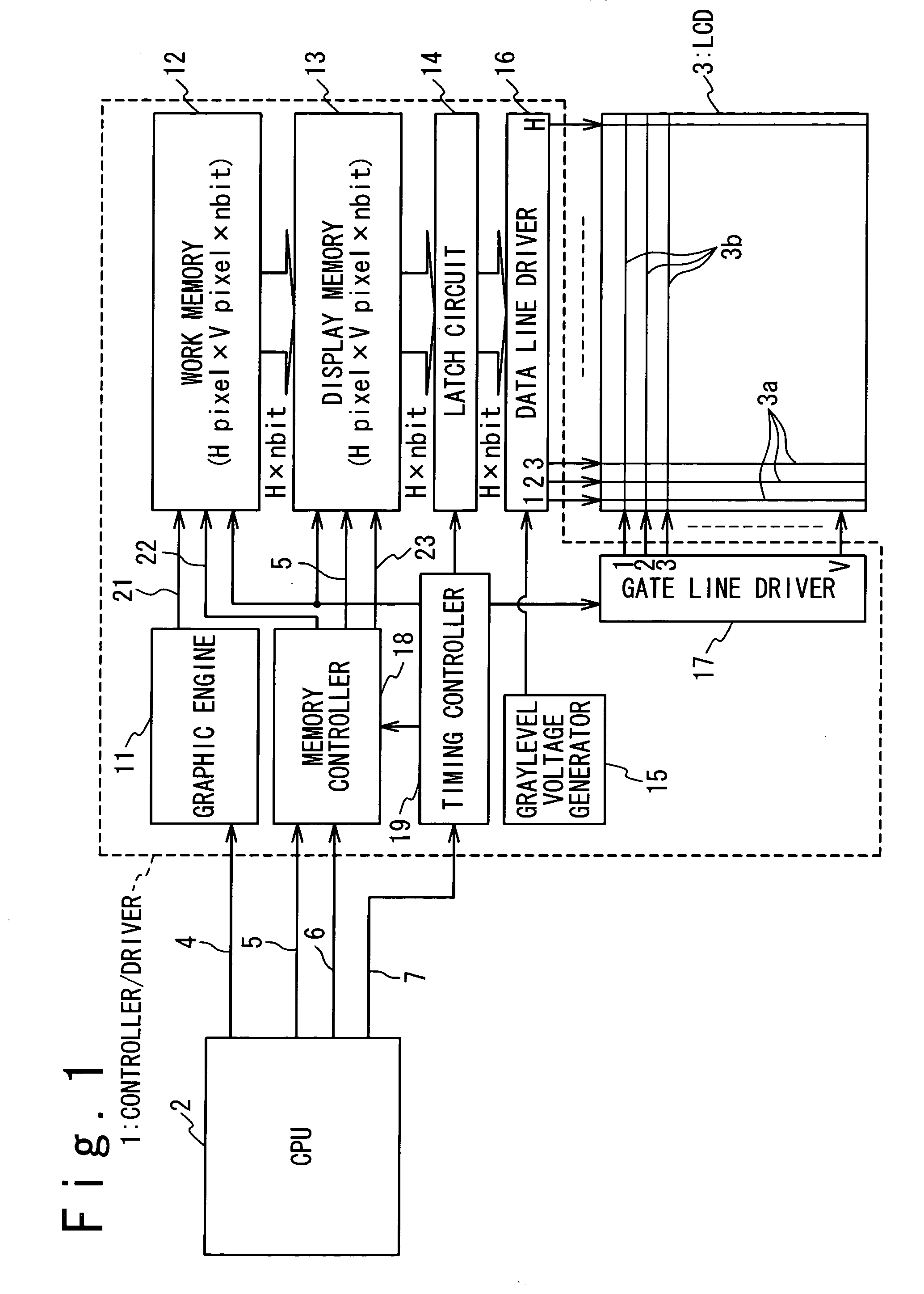
A controller/driver is composed of a work memory, a graphic engine, a display memory, and a driver circuit. The graphic engine converts externally received image data into first bitmap data, and stores the first bitmap data in the work memory. The display memory receives and stores second bitmap data developed from the first bitmap data stored in the work memory. The driver circuit drives a display panel in response to the second bitmap data received from the display memory.

Description

TECHNICAL FIELD [0001] The present invention is generally related to controller / drivers used for driving display panels, particularly, to controller / drivers including display memories for storing image data. BACKGROUND ART [0002] Controller / drivers used for driving display panels are often comprised of display memories for storing image data. Such controller / drivers receive image data representing images to be display on display panels from image processors, and temporally store the received image data into display memories. The controller / drivers are responsive to the image data stored in the display memories for driving data lines of display panels. [0003] In order to achieve increased grayscale capacity and improved smoothness of moving pictures, increased image data are required to be provided for controller / drives. Increase in the number of the graylevels of image data requires the number of data bits of image data for each pixel, and this leads to the increase in the amount of...

Claims


Application Information

Patent Timeline
IPC IPC(8): G09G3/36G06F3/14G09G3/20G09G5/34G09G5/36G09G5/393G09G5/397G09G5/40G11C11/413
CPCG06F3/14G11C11/413G09G3/2018G09G3/2025G09G3/2048G09G3/2051G09G3/2055G09G3/3648G09G3/3666G09G3/3688G09G5/346G09G5/363G09G5/393G09G5/397G09G5/40G09G2320/0257G09G2320/0285G09G2320/106G09G2340/02G09G2340/10G09G3/2011G09G3/36G09G5/39
Inventor FURIHATA, HIROBUMIOOHASHI, KATSUHISASHIODA, JUNYOUTESHIROGI, YOSHIYUKINOSE, TAKASHITUOMI, MIKA
Owner RENESAS ELECTRONICS CORP
Why Eureka
Try Eureka