Droplet dispensation from a reservoir with reduction in uncontrolled electrostatic charge

a technology of electrostatic charge and droplet, which is applied in the field of droplet dispensing from a reservoir with reduction of uncontrolled electrostatic charge, can solve the problems of unavoidable fluid waste, uncontrolled fluid transfer, and certain inherent characteristics of conventional fluid handling systems, and achieve the effects of reducing uncontrolled electrostatic charge, and reducing or eliminating uncontrolled electrostatic charg

Inactive Publication Date: 2006-11-02
LABCYTE
View PDF32 Cites 6 Cited by
  • Summary
  • Abstract
  • Description
  • Claims
  • Application Information

AI Technical Summary

Benefits of technology

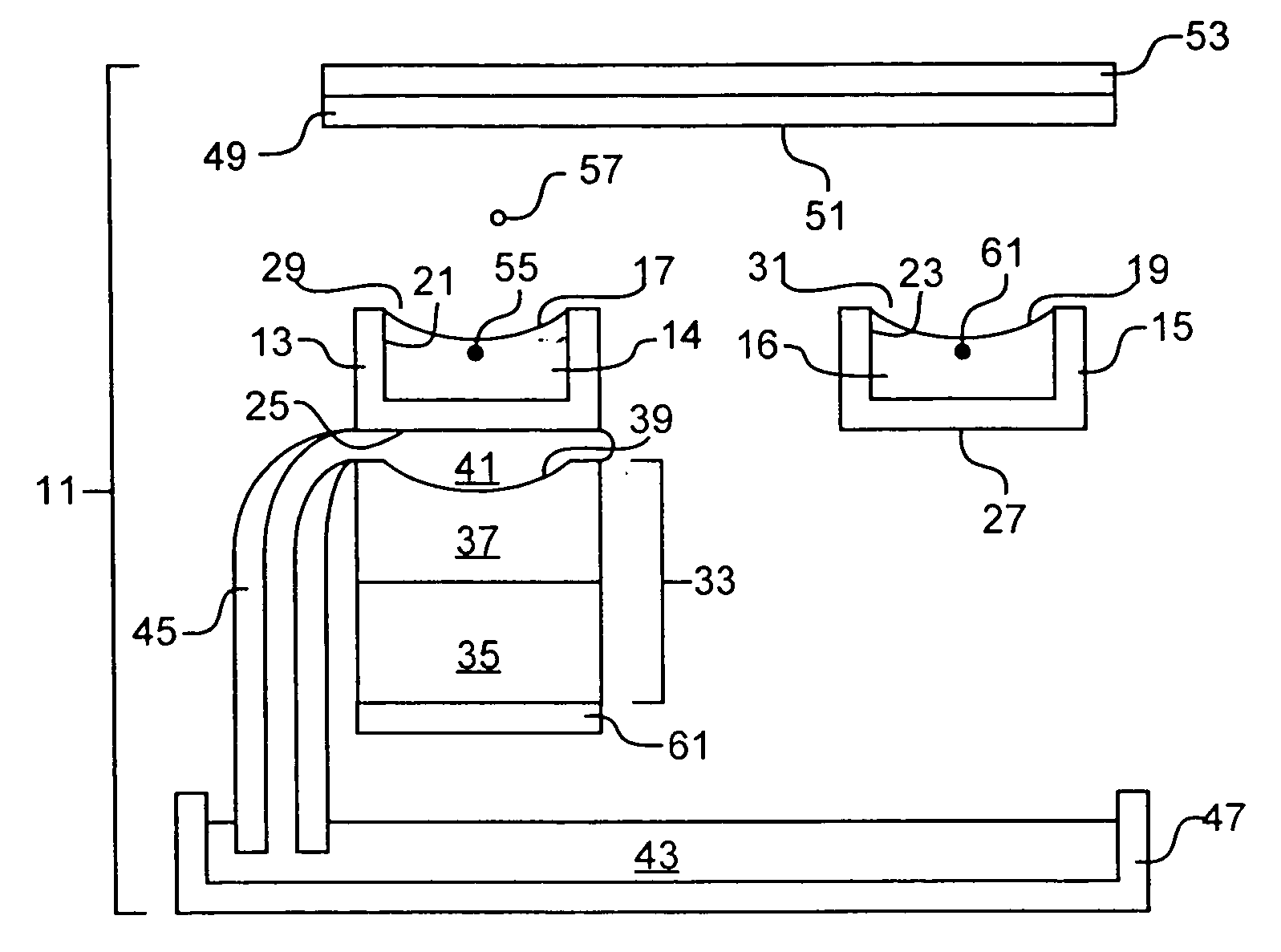
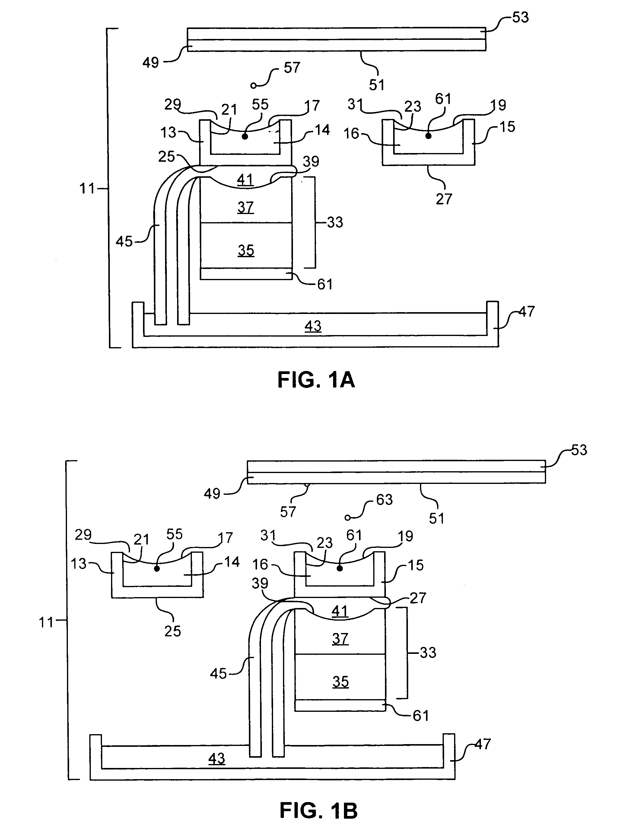
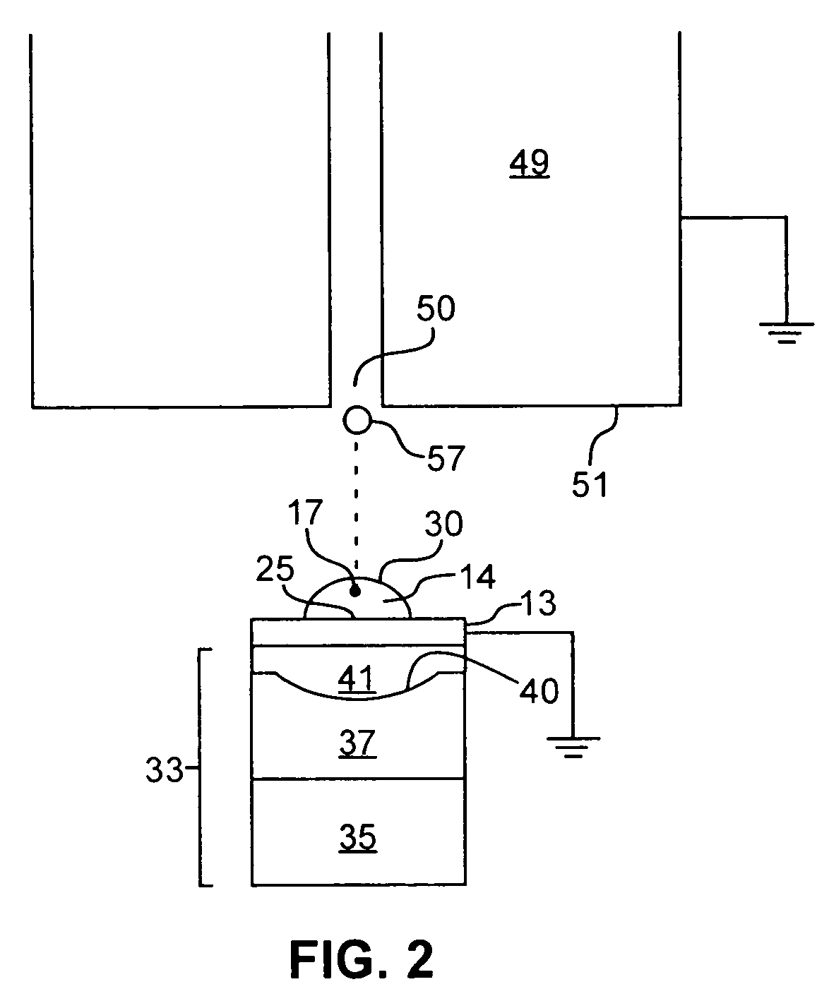
[0012] Accordingly, it is an object of the present invention to provide devices and methods that overcome the above-mentioned disadvantages of the prior art. In one embodiment, the invention provides a device comprised of a reservoir adapted to contain a fluid and a dispenser for dispensing a fluid droplet from the reservoir. A means is employed for reducing uncontrolled electrostatic charge on the reservoir when the reservoir is prone to accumulate uncontrolled electrostatic charge that alters the volume and / or trajectory of a droplet dispensed therefrom. The means for reducing uncontrolled electrostatic charge is effective to ensure that the volume and / or trajectory of the dispensed droplet do not substantially deviate from a predetermined volume and / or predetermined trajectory. Often grounding is used to reduce or eliminate uncontrolled electrostatic charge.
[0015] In a further embodiment, the invention provides a method for dispensing a droplet from a reservoir containing a fluid. The method involves reducing uncontrolled electrostatic charge on the reservoir when the reservoir is prone to accumulate uncontrolled electrostatic charge that alters the volume and / or trajectory of a droplet dispensed therefrom. As a result, uncontrolled electrostatic charge is reduced to a level effective to ensure that the volume and / or trajectory of the dispensed droplet do not substantially deviate from a predetermined volume and / or predetermined trajectory.

Problems solved by technology

Such conventional fluid handling systems, however, exhibit certain inherent disadvantages.
Such contact typically results in surface wetting that causes unavoidable fluid waste, a notable drawback when the fluid to be transferred is rare and / or expensive.
When fluid dispensing systems are constructed using networks of tubing or other fluid transporting conduits, air bubbles can be entrapped or particulates may become lodged in the networks.
Nozzles of ordinary inkjet printheads are also subject to clogging, especially when used to eject a macromolecule-containing fluid at elevated temperatures, a situation commonly associated with such technologies.
As a result, ordinary fluid dispensing technologies are prone to produce improperly sized or misdirected droplets.
In contrast to inkjet printing devices, focused acoustic radiation may be used to effect nozzleless fluid ejection, and devices using focused acoustic radiation are not generally subject to clogging and the disadvantages associated therewith, e.g., misdirected fluid or improperly sized droplets.
Although it is sometimes a straightforward matter to use electric fields to control the size and trajectory of droplet ejected from a single reservoir, it is quite difficult to achieve such control in high-throughput applications.
For example, when acoustic ejection is employed to transfer fluids from a 96-well source plate to a 384-well target plate, the relative motion between the plates makes it difficult to maintain the presence of a consistent charge within each well over time.
In addition, it has been discovered that wells of commercially available well plates, particularly those made from plastic materials such as polypropylene, polystyrene, or cyclic olefins, are often prone to accumulate uncontrolled electrostatic charge.
Uncontrolled electrostatic charge tends to alter the volume and / or trajectory of droplets dispensed from well plates.

Method used


Image

  • Droplet dispensation from a reservoir with reduction in uncontrolled electrostatic charge
  • Droplet dispensation from a reservoir with reduction in uncontrolled electrostatic charge
  • Droplet dispensation from a reservoir with reduction in uncontrolled electrostatic charge

Examples


example 1

[0091] A solution containing 70% by volume dimethylsulfoxide and 30% by volume water was placed within each well of a polystyrene well plate containing 384 substantially identical wells. An acoustic ejector having an F2 lens that served to focus acoustic radiation was placed in acoustic coupling relationship successively with each reservoir in substantially the same manner. Without removing uncontrolled electrostatic charge from the well plate, acoustic radiation having a frequency of 10 MHz was directed by the F2 lens into each reservoir so as to eject at least one droplet from each well. In some instances, secondary or satellite droplets were produced in addition to the primary droplets. The primary droplets exhibited a volume variation of over 25% as well as variations in trajectory.

example 2

[0092] Each well of the same polystyrene well plate described in Example 1 was again filled with a solution containing 70% by volume dimethylsulfoxide and 30% by volume water. However, uncontrolled electrostatic charge was removed from the well plate using an ionizer before the acoustic ejector was placed in acoustic coupling relationship successively with each reservoir. Acoustic radiation of having a frequency of 10 MHz was again directed by the F2 lens into each reservoir so as to eject at least one droplet from each well. No secondary or satellite droplets were produced. The primary droplets exhibited a volume variation of less than about 2%. No variations in the trajectory of the droplets were observed.


PUM


Abstract

Devices and methods are provided for reducing the uncontrolled electrostatic charges that can alter the volume and / or trajectory of a droplet, which is typically ejected through the application of focused acoustic radiation. Also provided are reservoirs and substrates, e.g., well plates formed from a material that is at least partially nonmetallic or polymeric and either has an electrical resistivity of no more than about 1011 ohm-cm, has a surface electrical resistivity of no more than about 1012 ohm / sq, or both.

Description

CROSS-REFERENCE TO RELATED APPLICATIONS [0001] This application is a divisional of U.S. patent application Ser. No. 10 / 340,557, filed Jan. 9, 2003, which is incorporated by reference herein.TECHNICAL FIELD [0002] This invention relates generally to devices and methods for accurately dispensing a droplet from a reservoir, optionally toward a substrate, wherein the volume and / or trajectory of the droplet do not substantially deviate from a predetermined volume and / or trajectory. More particularly, the invention relates to devices and methods for reducing the uncontrolled electrostatic charges that can alter the volume and / or trajectory of a droplet, which is typically ejected through the application of focused acoustic radiation. BACKGROUND [0003] There exists a need in pharmaceutical, biotechnological, medical, and other industries to be able to quickly screen, identify, analyze, and / or process large numbers or varieties of fluids. As a result, much attention has been focused on deve...

Claims


Application Information

Patent Timeline
Patent Type & Authority Applications(United States)
IPC IPC(8): B41J2/015B41J2/045B41J2/14
CPCB41J2/04511B41J2/14008B41J2/04575B41J2/04526
Inventor MUTZ, MITCHELL W.LEE, DAVID SOONG-HUAMCLENDON, GEORGE
Owner LABCYTE
Why Eureka
Try Eureka