

Light scattering type particle detector
a particle detector and light scattering technology, applied in the field of light scattering type particle detectors, can solve the problems of considerable large-scale elements for controlling the temperature of semiconductor lasers b>100/b>
- Summary
- Abstract
- Description
- Claims
- Application Information
AI Technical Summary
Problems solved by technology
Method used
Image

Examples
first embodiment
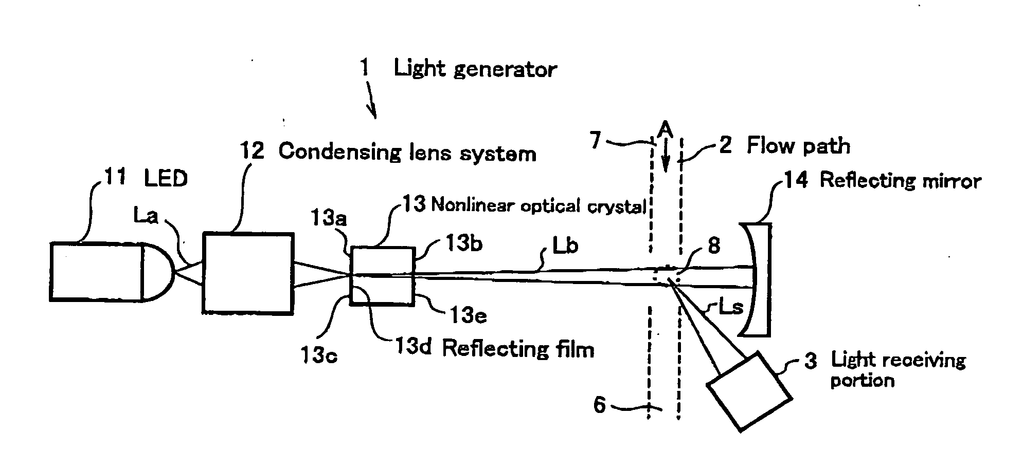
[0016] As shown in FIG. 1, the light scattering type particle detector is comprised of a light generator 1 for generating light Lb, a flow path 2 which is defined by fluid to be monitored, and a light receiving portion 3 for receiving scattered light Ls.
[0017] The light generator 1 comprises a light-emitting diode (LED) 11 for emitting light La having a wavelength of λ as a light source, a condensing lens system 12 for condensing the light La emitted from the LED 11, a nonlinear optical crystal 13 for emitting a second harmonic (light Lb having a wavelength of λ / 2) by receiving the light La having a wavelength of λ condensed with the condensing lens system 12, and a reflecting mirror 14 for reflecting the light Lb having a wavelength of λ / 2 emitted from the nonlinear optical crystal 13 to reflect the light Lb back to the nonlinear optical crystal 13. The nonlinear optical crystal 13 and the reflecting mirror 14 which oppose one another with the particle detecting area interposed th...
second embodiment
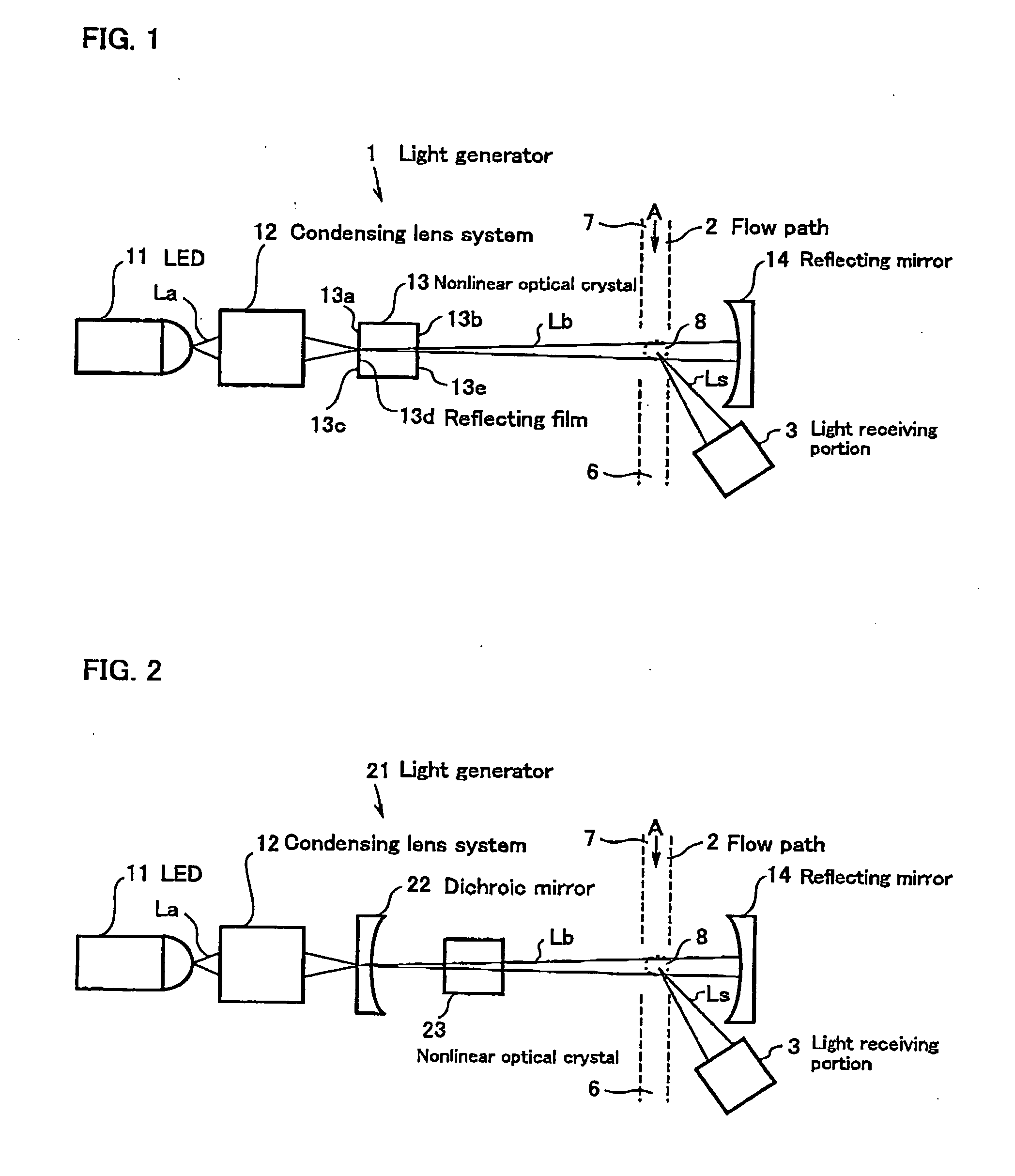
[0028] As shown in FIC 2, the light scattering type particle detector is comprised of a light generator 21 for generating light Lb, a flow path 2 which is defined by fluid to be monitored, and a light receiving portion 3 for receiving scattered light Ls.
[0029] The light generator 21 comprises a light-emitting diode (LED) 11 for emitting light La having a wavelength of λ as a light source, a condensing lens system 12 for condensing the light a emitted from the LED 11, a dichroic mirror 22 for transmitting the light La condensed with the condensing lens system 12, a nonlinear optical crystal 23 for emitting a second harmonic (light Lb having a wavelength of λ / 2) by receiving the light La having a wavelength of λ transmitted through the dichroic mirror 22, and a reflecting mirror 14 for reflecting the light Lb having a wavelength of λ / 2 emitted from the nonlinear optical crystal 23 to reflect the light Lb back to the dichroic mirror 22. The nonlinear optical crystal 23 and the reflect...
third embodiment
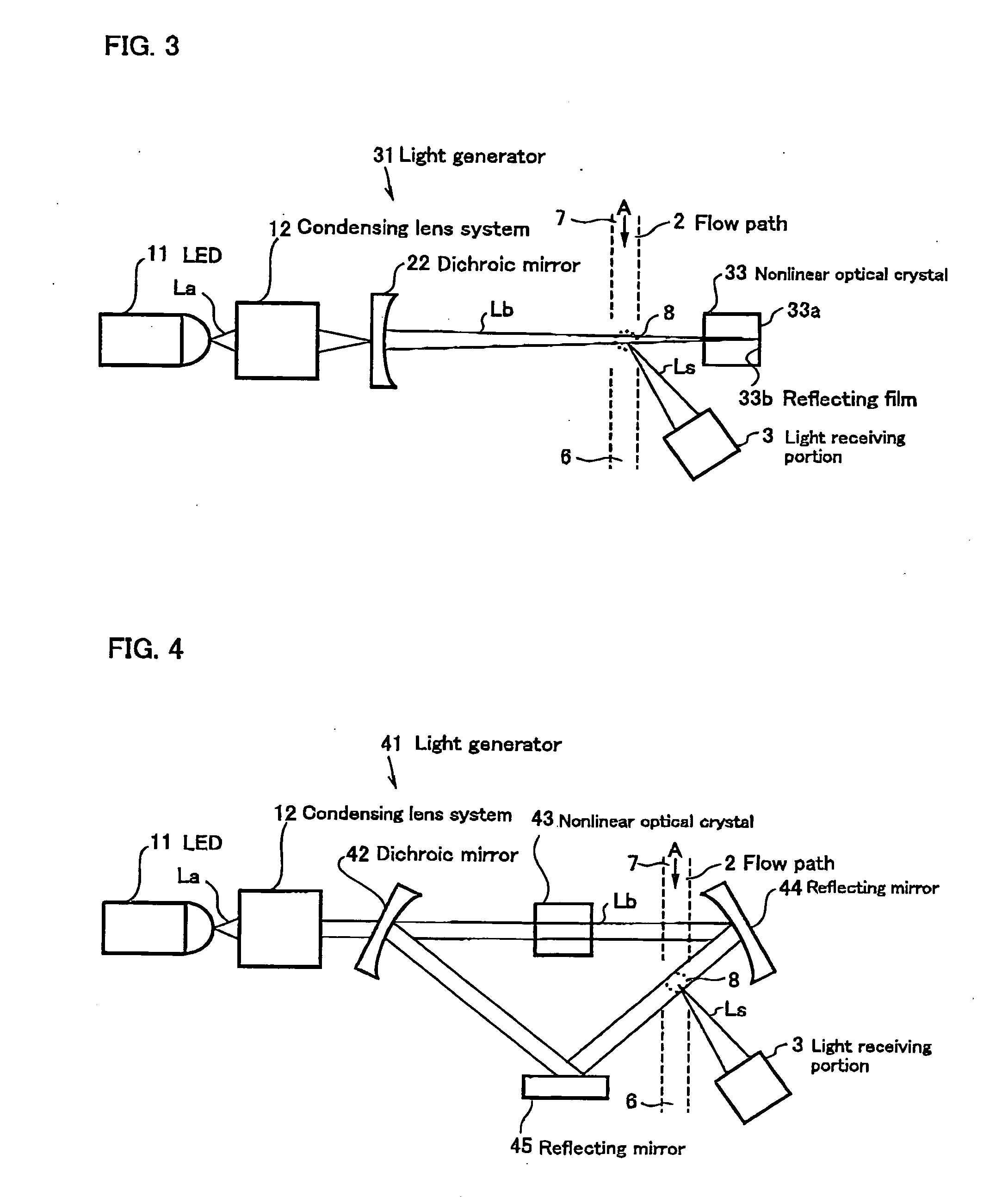
[0038] As shown in FIG. 3, the light scattering type particle detector is comprised of a light generator 31 for generating light Lb, a flow path 2 which is defined by fluid to be monitored, and a light receiving portion 3 for receiving scattered light Ls.
[0039] The light generator 31 comprises a light-emitting diode (LED) 11 for emitting light La having a wavelength of λ as a light source, a condensing lens system 12 for condensing the light La emitted from the LED 11, a dichroic mirror 22 for transmitting the light La condensed with the condensing lens system 12, and a nonlinear optical crystal 33 for emitting a second harmonic (light Lb having a wavelength of λ / 2) by receiving the light La having a wavelength of λ transmitted through the dichroic mirror 22.
[0040] The nonlinear optical crystal 33 can also emit a fundamental harmonic (light La having a wavelength of λ), a third harmonic (light having a wavelength of λ / 3), a fourth harmonic (light having a wavelength of λ / 4) and so...
PUM
| Property | Measurement | Unit |
|---|---|---|
| wavelength | aaaaa | aaaaa |
| wavelength | aaaaa | aaaaa |
| converted wavelength | aaaaa | aaaaa |
Abstract
Description
Claims
Application Information