Detection device

a detection device and detection technology, applied in the direction of counting objects on conveyors, distance measurement, instruments, etc., to achieve the effect of adequate scan control and high precision

Inactive Publication Date: 2006-11-02
SANYO ELECTRIC CO LTD
View PDF9 Cites 24 Cited by
  • Summary
  • Abstract
  • Description
  • Claims
  • Application Information

AI Technical Summary

Benefits of technology

[0009] An object of the present invention is to provide a detection device capable of detecting movement of an obstacle and a state t

Problems solved by technology

However, JP 11-325885 A does not describe how to control a laser beam scan st

Method used


Image

  • Detection device
  • Detection device
  • Detection device

Examples


first embodiment

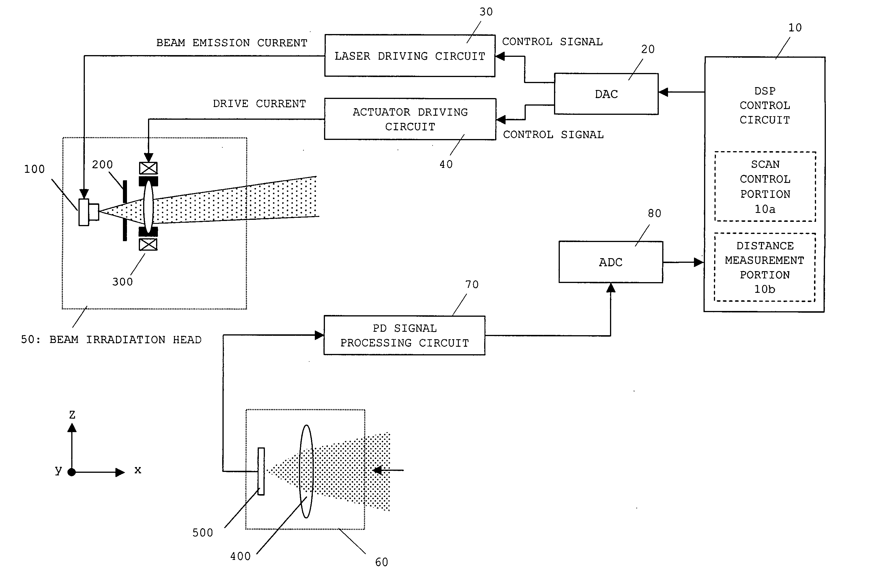
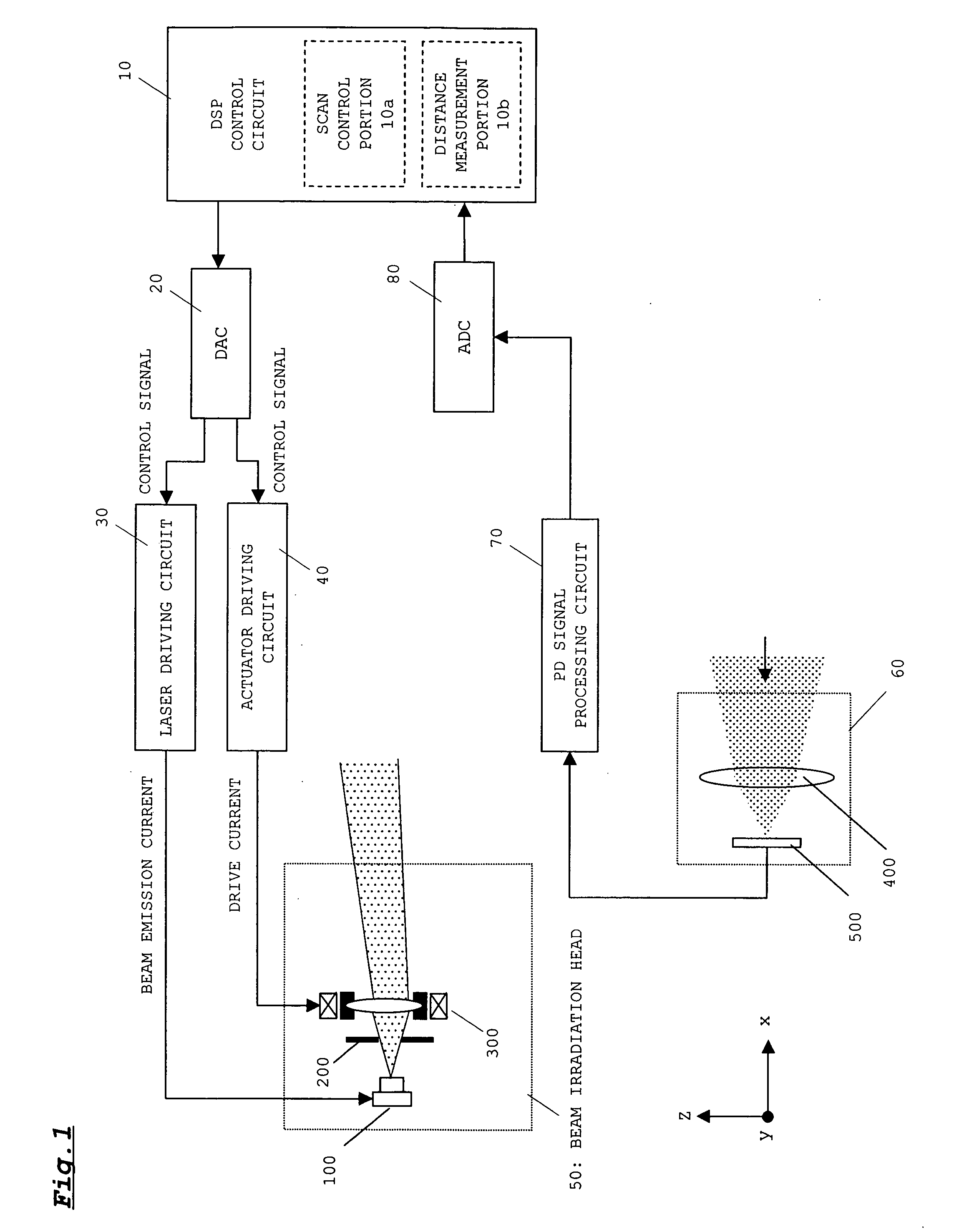
[0050]FIG. 1 shows the configuration of a beam irradiation device according to a first embodiment of the present invention.

[0051] A beam irradiation device is provided with a digital signal processor (DSP) control circuit 10, a digital analog converter (DAC) 20, a laser driving circuit 30, an actuator driving circuit 40, a beam irradiation head 50, a beam receiving portion 60, a photo detector (PD) signal processing circuit 70 and an analog digital converter (ADC) 80.

[0052] The DSP control circuit 10 outputs a digital signal for performing drive control of the laser driving circuit 30 and the actuator driving circuit 40 to the DAC 20. Also, The DSP control circuit 10 detects the position of an obstacle in a scanning region and measures a distance to the obstacle based on the digital signal input from ADC 80. A scan control portion 10a and a distance measurement portion 10b are provided in the DSP control circuit 10.

[0053] Signals relating to the steering direction and speed of th...

second embodiment

[0107] A beam irradiation device according to a second embodiment of the present invention detects difference between a target position and an irradiation position of laser beam by monitoring the laser beam emitted from the semiconductor laser to correct scan trajectory of the laser beams based on the detection result.

[0108]FIG. 10 shows the configuration of the beam irradiation device. As shown in FIG. 10, the beam irradiation device is provided with a position sensitive detector (PSD) signal processing circuit 90 in addition to the configuration of the first embodiment. Also, the beam irradiation head according to the second embodiment is provided with a beam splitter 600, a converging lens 700 and a PSD 800 in addition to the configuration of the beam irradiation head of the first embodiment.

[0109] Explanation relating to the same configuration as the first embodiment will be omitted and explanation will be made relating to the configuration to differ from the first embodiment ...


PUM


Abstract

An irradiation pattern of a laser beam within a target region is controlled based on external signals each related to a driving direction and a driving speed, a result obtained by detection of an obstacle, and signals related to distances to the obstacle. For example, at the time of a right turn, an irradiation pattern for increasing irradiation frequency on a portion shifted in a right-turn direction from a center axis in a driving direction is set. At the time of high-speed driving, an irradiation pattern for increasing irradiation frequency on a center portion of a forward region in the driving direction is set. When the obstacle is detected and a distance to the obstacle is shorter than a threshold distance, an irradiation pattern for increasing irradiation frequency in the vicinity of the obstacle is set. Detection of the obstacle and monitoring of a state thereof are adequately and smoothly performed at the time of changing of the driving direction, the time of high-speed driving, and the time of detection of the obstacle.

Description

BACKGROUND OF THE INVENTION [0001] 1. Field of the Invention [0002] The present invention relates to a detection device for detecting an obstacle within a target region by emitting a laser beam to the target region, which is suitable, for example, to be mounted on a moving object such as a vehicle or an airplane. [0003] 2. Description of the Related Art [0004] In recent years, vehicle-to-vehicle distance detectors and distance detectors using laser beams have been employed in various devices. A vehicle-to-vehicle distance detector, for example, detects the presence or absence of an obstacle and measures a distance to the obstacle by detecting reflected beams that are obtained when laser beams are radiated from a front portion of a vehicle. [0005] In this case, the laser beams are caused to longitudinally and laterally scan a target region preset in a front space. A time difference between timing for radiating the laser beams and timing for receiving the reflected beams is measured a...

Claims


Application Information

Patent Timeline
IPC IPC(8): G01B11/14
CPCG01S7/481G01S17/936G01S7/4972G01S17/931
Inventor YAMADA, MASATOICHIURA, SHUICHI
Owner SANYO ELECTRIC CO LTD
Why Eureka
Try Eureka