Perforated plate for water chuck

a technology of perforated plates and water chucks, applied in the field of perforated plates, can solve the problems of common drop or breakage, and achieve the effect of improving reliability

Inactive Publication Date: 2006-11-02
SYST ON SILICON MFG PTE
View PDF11 Cites 8 Cited by
  • Summary
  • Abstract
  • Description
  • Claims
  • Application Information

AI Technical Summary

Benefits of technology

[0007] The object of at least one aspect of the present invention is to provide a perforated plate, or a chuck incorporating such a plate, for use in a wa

Problems solved by technology

With these and other prior art chucks, wafer slippages, drops or breakages are common, particularly when loading and unloading a wafer at a loading station,

Method used


Image

  • Perforated plate for water chuck
  • Perforated plate for water chuck
  • Perforated plate for water chuck

Examples


Embodiment Construction

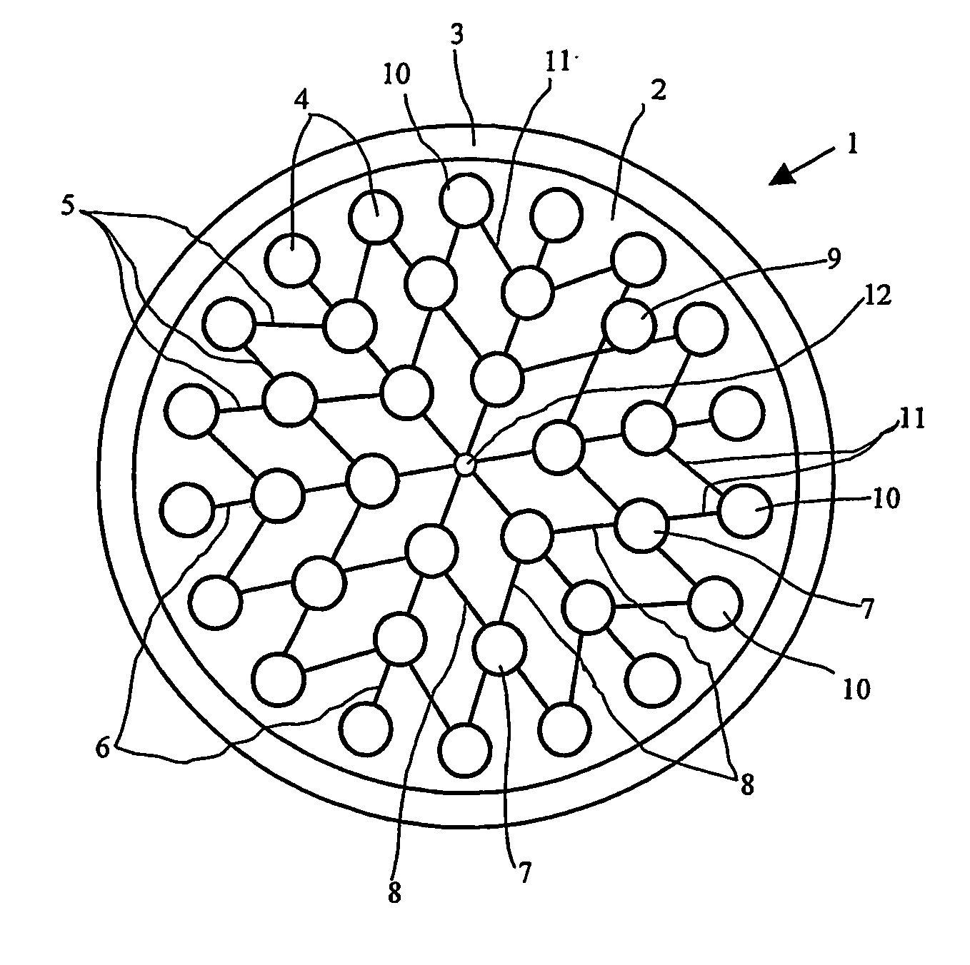
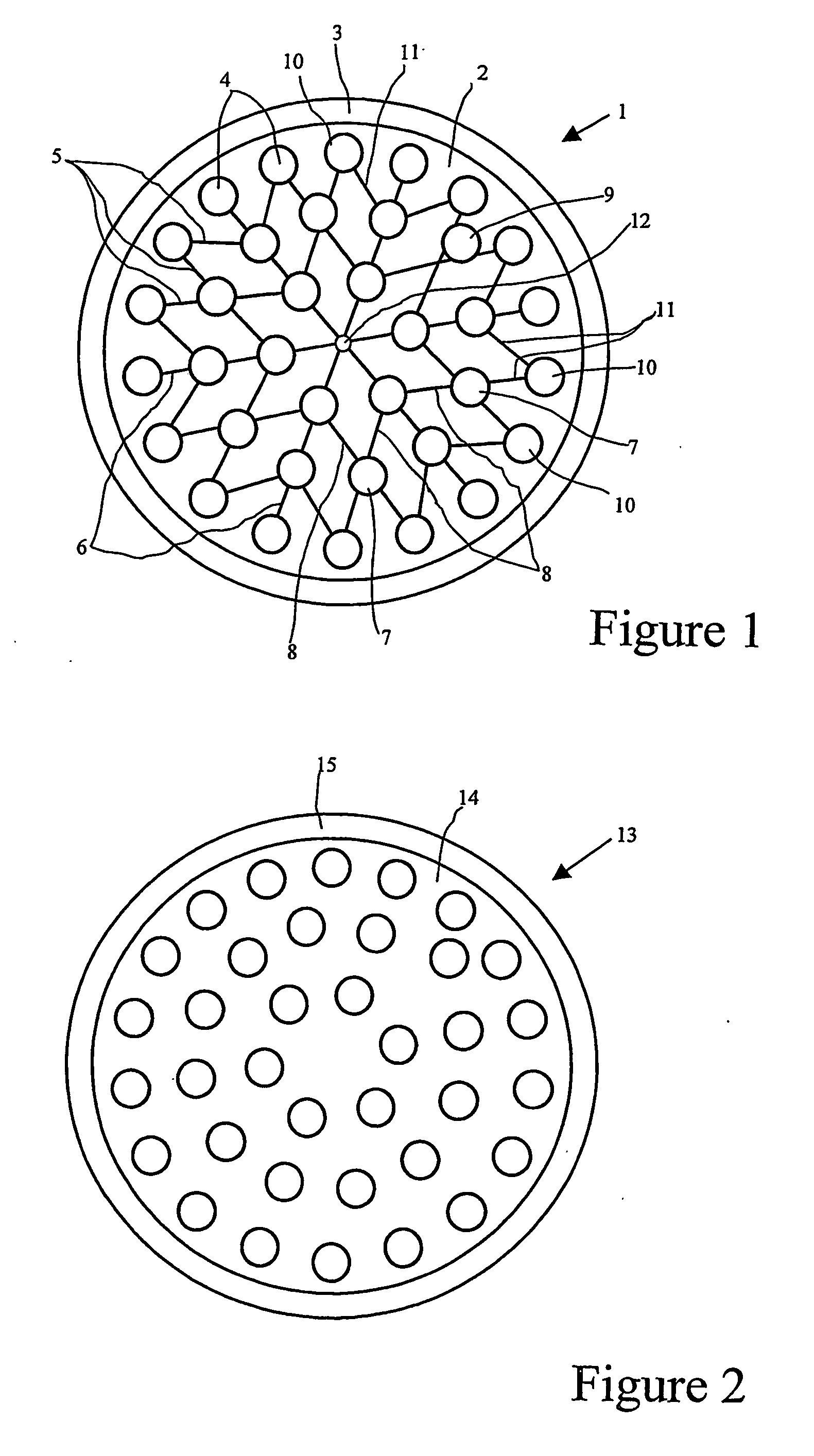
[0035]FIG. 1 shows a plan view of a circular perforated plate 1 according to the current invention. A first face 2 of the plate, i.e. the face shown in FIG. 1, has a thickened peripheral edge rim 3, but is otherwise is planar. The second, opposite face, i.e. the face not seen in FIG. 1, is planar. The rim contributes to the rigidity of the plate and assists in maintaining the planarity of the opposite faces of the plate. The opposite faces of the plate are parallel. The plate has a pattern of holes 4 which extend through the plate between the opposite faces.

[0036] In the preferred embodiment shown in FIG. 1, the through holes are interconnected by a pattern of grooves 5 in the first face. Each groove interconnects a respective pair of holes. Although other groove configurations may be used, it is preferred that the grooves be straight, as shown in FIG. 1, to provide the shortest possible groove length between the respective pairs of through holes.

[0037] The through holes are conve...


PUM


Abstract

A perforated plate for use in a wafer-handling chuck has a pattern of through holes by which a vacuum is applied to a membrane to form suctions cups that secure a wafer to the chuck. Grooves in a generally planar upper surface of the plate interconnect the through holes. The grooves ensure the maintenance of the vacuum, and the consequent formation of the membrane suction cups, at each through hole, even when the grooved surface of the plate is in close face-to-face contact with another planar surface in the chuck. In one embodiment, the through holes in the perforated plate lie on concentric circles and the grooves interconnect radially-outward through holes to the next closest one or pair or radially-inward through holes.

Description

FIELD OF INVENTION [0001] The present invention relates to improvements in perforated plates used in a wafer support or chuck system and particularly to such systems used to carry semiconductor wafers during fabrication, for example fabrication of integrated circuits and micro electro-mechanical devices, and more particularly during polishing or planarization of such wafers. BACKGROUND [0002] As part of the fabrication of a semiconductor wafer, a face of the wafer may be planarized by a chemical / mechanical polishing (CMP). This planarization may be used to reduce the thickness of the wafer itself, or of a layer built up or deposited on a face of the wafer. Alternatively, the surface of a patterned wafer may be made flat to maintain the photo-lithographic depth of focus for subsequent patterning steps and / or to limit deformation of subsequently deposited layers, e.g. metallization layers. [0003] The wafer is held in a chuck which presses the wafer against a rotating polishing pad in ...

Claims


Application Information

Patent Timeline
IPC IPC(8): H01T23/00B24B37/30B28D5/00H01L21/683
CPCB24B37/30H01L21/6838B28D5/0094
Inventor KOH, MENG FAIPOH, CHOON SIONGLEONG, TECKWEI, THENGWANG, BING
Owner SYST ON SILICON MFG PTE
Why Eureka
Try Eureka