Disc annulus repair system

a disc annulus and disc technology, applied in the field of medical devices, can solve the problems of reducing the shock absorption ability of the disc, pain and possibly sensory or motor problems, and traumatic vertebral column, and achieve the effect of increasing the disc axial heigh

Active Publication Date: 2006-11-02
JMEA CORP
View PDF99 Cites 34 Cited by
  • Summary
  • Abstract
  • Description
  • Claims
  • Application Information

AI Technical Summary

Benefits of technology

[0012] In some embodiments, the first anchor may include at least one projection extending away from the first end portion. The second anchor may include at least one barb. The prosthesis, in an installed position, may provide a circumferential force on the disc. The prosthesis may provide a hoop stress on the disc. The prosthesis may help to maintain or help to increase the axial height of the disc. The prosthesis may help to close the cut on the disc, and may also help to maintain nucleus material within the disc. It is also possible to provide an optional additional prosthesis in roughly the same location as the previous prosthesis. This additional prosthesis can be disposed at an angle different than the angle of the previous prosthesis. In some cases, the additional prosthesis can be vertically disposed.

Problems solved by technology

However, there are certain conditions, notably traumatic injury and vertebral column degeneration, that can cause problems.
This reduces the shock-absorbing ability of the disc, and may impinge on spinal or surrounding nerves, causing pain and possibly sensory or motor problems.
Moreover, trauma may cause an intervertebral disc to fail entirely, potentially causing all of the above problems, even if a particular weak spot in the nucleus purposus has not developed.
Any surgery to the vertebral column can be traumatic for the patient, and, depending on the area of the intervertebral column that is to be repaired, it can be difficult to access the area to make repairs.
It is very difficult to close the nucleus purposus effectively; therefore no attempt is currently made to close or repair this defect.

Method used


Image

  • Disc annulus repair system
  • Disc annulus repair system
  • Disc annulus repair system

Examples


Embodiment Construction

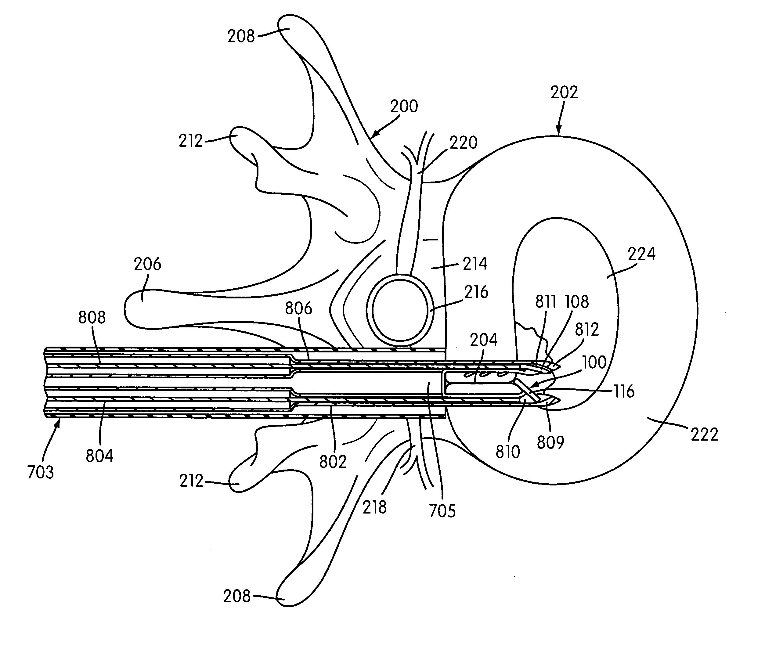
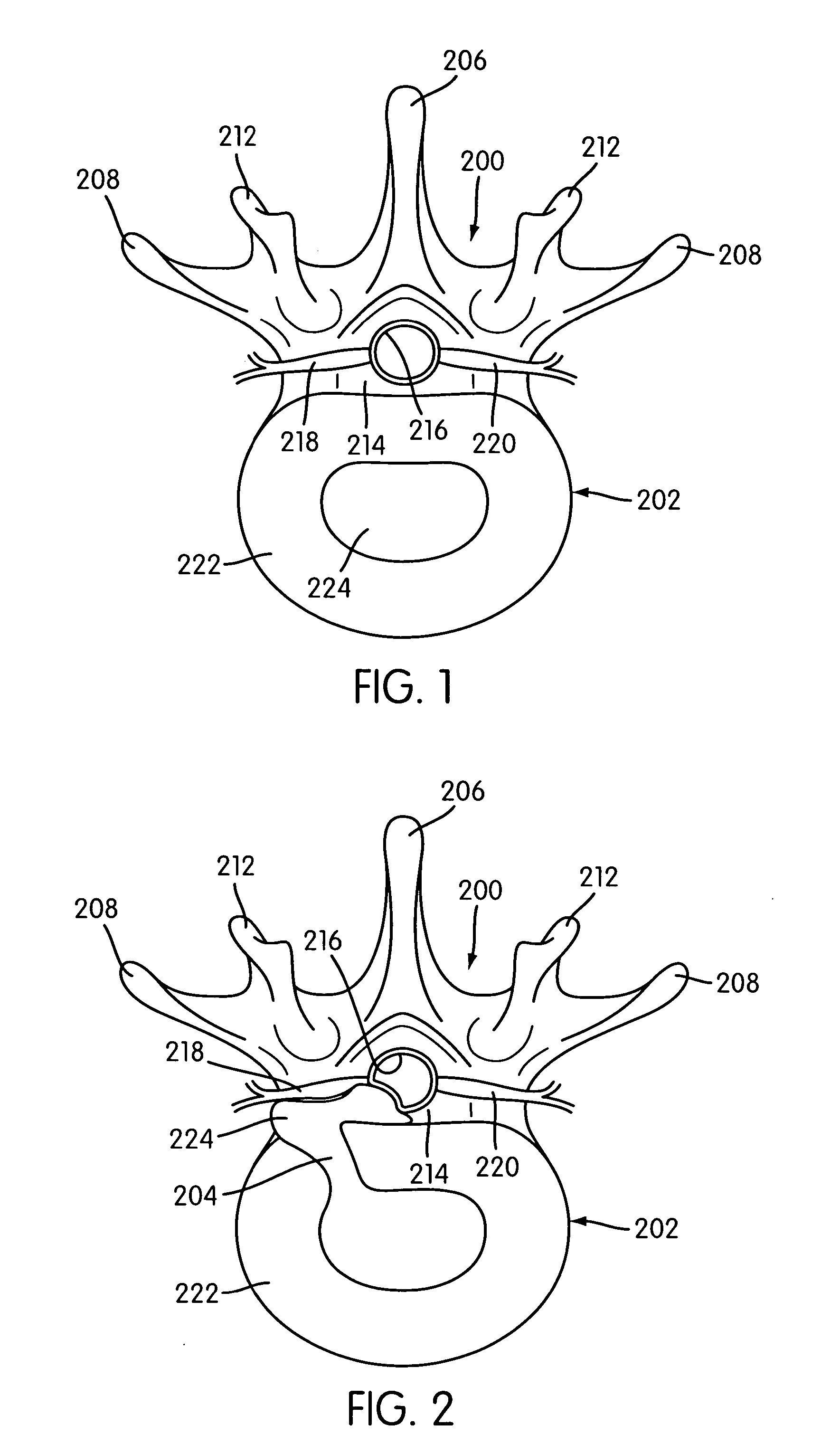
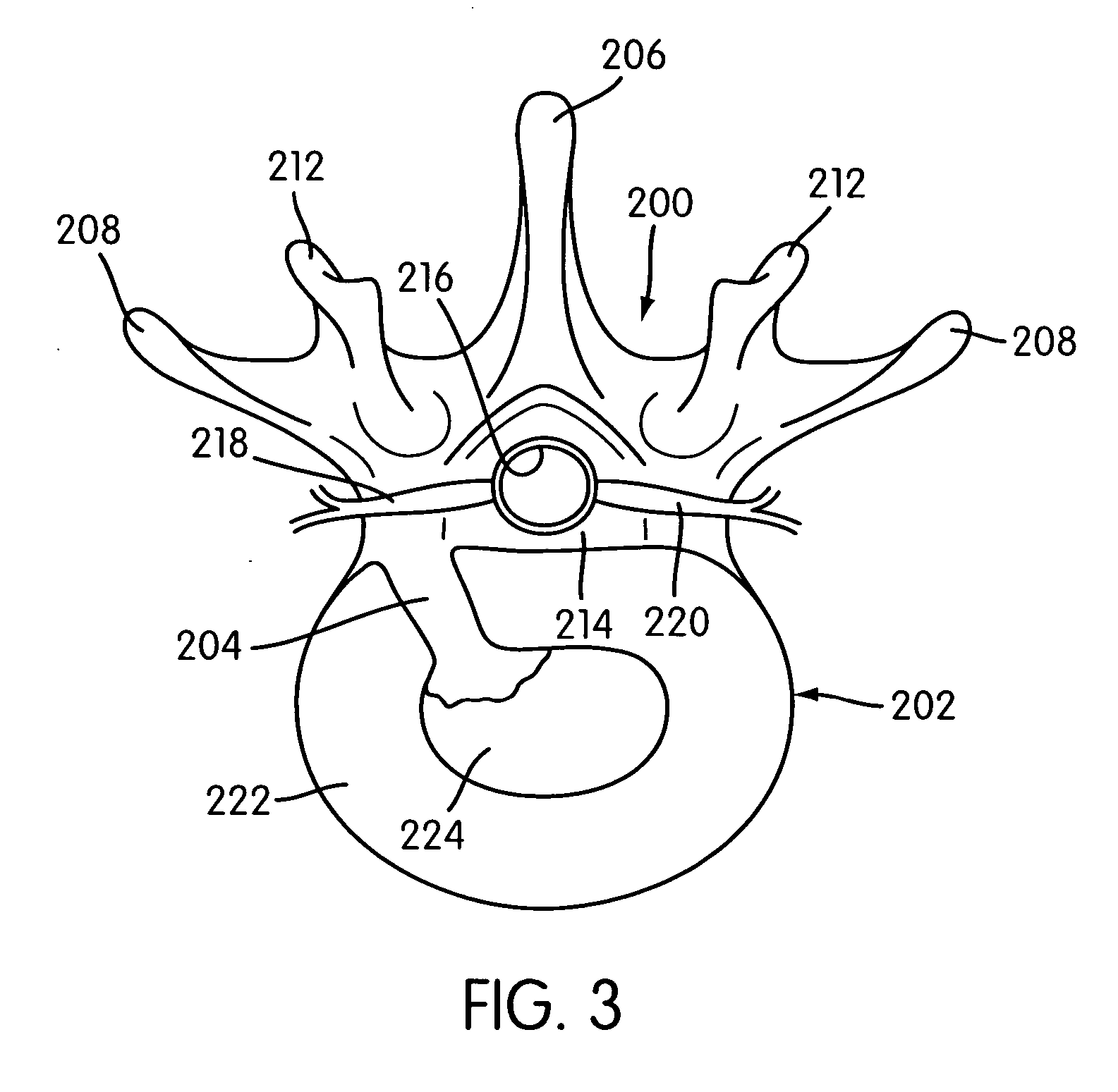
[0069]FIGS. 4-6 illustrate one embodiment of a closure prosthesis 100 that is adapted to close a flaw, imperfection, cut, incision, hole, or tear in an intervertebral disc 202. Specifically, FIGS. 4 and 5 are plan views of a single vertebra 200 and its associated intervertebral disc 202, illustrating the association of the closure prosthesis 100 with an intervertebral disc 202, and FIG. 6 is a perspective view illustrating the closure prosthesis 100 in isolation.

[0070] Although one particular embodiment of the closure prosthesis 100 is illustrated in those figures, the size, shape, and other characteristics of the closure prosthesis 100 may be determined based on a number of factors, potentially including the size and shape of the imperfection; the condition and type of tissue into which the closure prosthesis 100 is to be deployed; and the type and amount of circumferential or other stress that is to be exerted by the closure prosthesis 100 on the surrounding tissue. Recall that t...


PUM


Abstract

A repair system including a closure prosthesis and deployment device, and associated methods for repairing any imperfection including a flaw, hole, tear, bulge, or, in some cases, a deliberate cut or incision in any tissue including an intervertebral disc. The prosthesis has first and second side portions with a connecting central portion, and is designed to span an imperfection with opposite ends positioned on opposite sides of the imperfection. The prosthesis may include anchoring features including barbs and/or members that extend transversely. The deployment device can include a canula for positioning the prosthesis near the imperfection, and, in some cases, a mechanism that may cause the two sides of the prosthesis to be deployed in a specific order.

Description

CROSS REFERNCE TO RELATED APPLICATIONS [0001] This application is a continuation of U.S. patent Ser. No. ______ now U.S. patent application Ser. No. 11 / 117,704, filed on Apr. 29, 2005, entitled: “Tissue Repair System,” the entirety of which is hereby incorporated by reference.BACKGROUND OF THE INVENTION [0002] 1. Field of the Invention [0003] The invention relates generally to medical devices, and more particularly, to medical devices for repair of tissue, including intervertebral discs. [0004] 2. Description of Related Art [0005] The spinal cord is the body's main nerve pathway, extending from the base of the skull down the back toward the lower (sacral) region of the back, where it branches. The spinal cord is protected from injury and damage by the vertebral column, a flexible column comprised of bones called vertebrae, which encircle and enclose the spinal column. Most of the vertebrae in the spinal column are interspersed with intervertebral discs, which are compliant discs, ea...

Claims


Application Information

Patent Timeline
Patent Type & Authority Applications(United States)
IPC IPC(8): A61B17/84A61F2/44A61F2/46
CPCA61B17/0642A61B17/0682A61B17/10A61B2017/0409A61B2017/0419A61F2230/0013A61F2002/30131A61F2002/30841A61F2002/4435A61F2002/4627A61F2/4611
Inventor BHATNAGAR, MOHIT K.YEH, JACK Y.SACK, JAMESWOODS, RICHARD W.
Owner JMEA CORP
Why Eureka
Try Eureka