In-situ intervertebral fusion device and method

a fusion device and in-situ technology, applied in the field of in-situ intervertebral fusion device and method, can solve the problems of inconvenient use of fusion device or bone graft substitute designed for promoting bony fusion at another location in the body, may not be suitable for use as an intervertebral body fusion device, and may cause lower back pain. , to achieve the effect of increasing disc height, minimal invasiveness and reducing pain

Active Publication Date: 2012-12-06
DEPUY SYNTHES PROD INC +1
View PDF12 Cites 174 Cited by
  • Summary
  • Abstract
  • Description
  • Claims
  • Application Information

AI Technical Summary

Benefits of technology

[0035]The advantages of the present invention are numerous. One advantage is that the present invention makes possible minimally invasive surgical procedures to restore a natural angle and increase disc height between two adjacent vertebrae. Furthermore, the same device used to create distraction / lordosis can function as the intervertebral implant needed to maintain height and natural angle. Another advantage is that the present invention makes possible a minimally invasive procedure to create in situ a structural scaffold filled with osteoinductive materials.

Problems solved by technology

A leading cause of lower back pain arises from lumbar intervertebral disc pathology, including rupture or degeneration of the disc.
Additionally, lower back pain may be caused by collapse of the disc and the dysarthrosis of an unstable or degenerative vertebral facet joint.
Accordingly, a fusion device or bone graft substitute designed for promoting bony fusion at another location in the body (such as long bone fusion) may not be suitable for use as an intervertebral body fusion device.
However, such gels typically do not posses the stiffness or mechanical strength found to be required for lumbar intervertebral fusion devices.
In general, delivery of conventional intervertebral fusion devices has required significantly invasive implantation procedures.
Open anterior surgery in the lumbar spine is very risky due to the close proximity of sensitive vascular structures, such as the aorta and bifurcation of the aorta.
Furthermore, the anterior open procedure can cause significant scar formation on the spine, making anterior revision surgery, if necessary, even more risky.
However, current techniques require appreciable surgical expertise and can significantly increase surgery time.
Furthermore, insertion of interbody fusion cages through minimally invasive means often requires high insertion forces.
However, the requirements for a bone fusion system are very different from those of injectable prosthetic devices.

Method used


Image

  • In-situ intervertebral fusion device and method
  • In-situ intervertebral fusion device and method
  • In-situ intervertebral fusion device and method

Examples


example 1

Employing a Method of the Present Invention

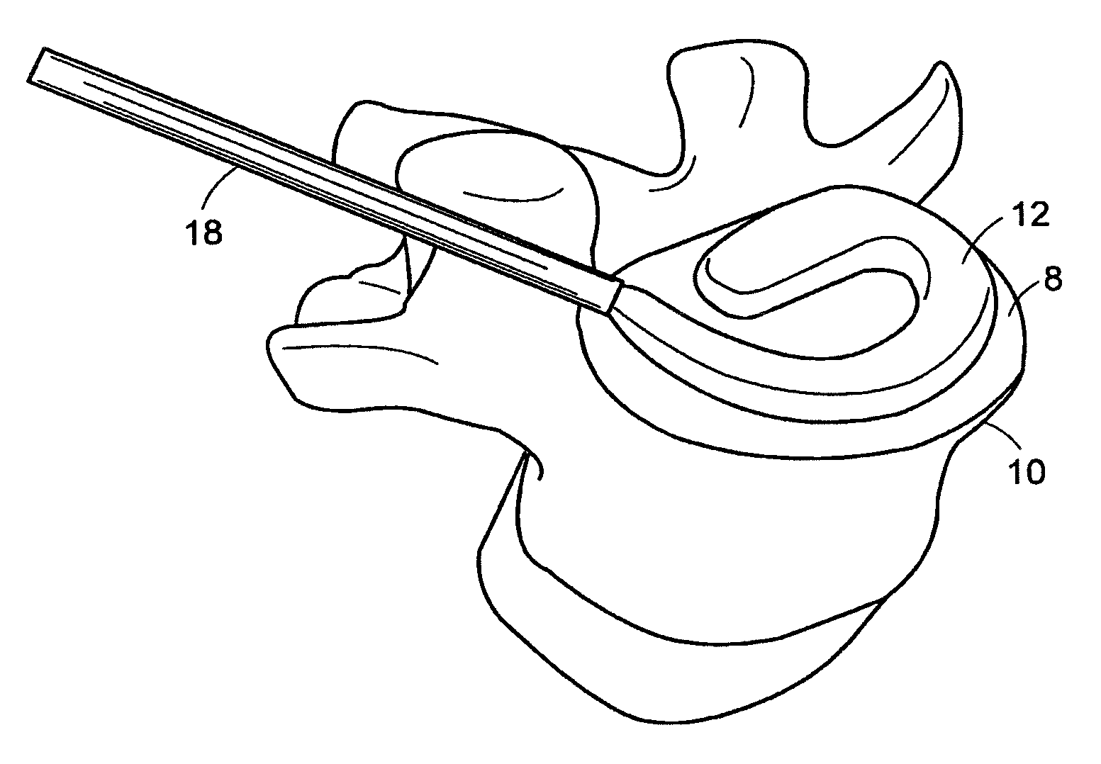
[0535]In performing a preferred method of the present invention, the patient is brought to the pre-surgical area and prepped. Anesthesia is then induced and the area of the spine is further prepped. A small incision through the muscles is opened under dissecting microscopic visualization. The incision is made as small as possible and is longitudinal in the plane of the spine. The paravertebral muscles are separated by blunt dissection and held apart with forceps and dividers. The intervertebral disc area is visualized, with initial exposure down to the lamina. The area below the lamina, at the point of the intervertebral foramina, can also be exposed.

[0536]The disc is examined for extruded material and any extruded material is removed. Magnetic resonance imaging (“MRI”) data can be used to determine the integrity of the annulus fibrosis at this point. An arthroscope is inserted into the disc and used to examine the inside of the annulus. Op...

example 2

A Surgical Procedure that Employs Methods and Devices of the Present Invention

[0543]A surgical procedure to fuse the vertebrae using methods and devices of the present invention can comprise the following steps:[0544]i. Puncture or cut a flap in the annulus fibrosus and insert a small diameter tube into the slit,[0545]ii. Perform a conventional discectomy to remove the nucleus pulposus,[0546]iii. Insert a small diameter tube, e.g. a cannula, into the disc space through the slit,[0547]iv. Insert a strut, e.g. a balloon or a ramp having a partially annular shape, into the disc space through the tube,[0548]v. Flow glucose-containing polycaprolactone into the disc space including the volume defined by the outer surface of the partially annular balloon or a ramp, through the tube at about 70° C. Upon cooling to 37° C., the polycaprolactone should become solid, thereby supplementing the mechanical attributes of the strut,[0549]vi. Leach out the glucose, thereby forming a porous matrix.[05...

example 3

Harvesting Progenitor Cells for Use in Osteobiologic Material

[0553]Prior to performing spinal surgery, approximately 5 cc of bone marrow is aspirated from the iliac crest of the patient into a heparinized syringe tube. The heparinized marrow is then passed through a selective cell attachment filter. The filter is designed for selective attachment of osteoprogenitor cells such as mesenchymal stem cells and osteoblasts. Following selective cell attachment, the cells are tripsinized off of the filter and collected in a flask. The flask is then centrifuged to precipitate a cell pellet on the bottom of the flask and the supernatant is poured off. The cells are then mixed with the injectable precursor form of the hydrogel. The precursor hydrogel is then poured into molds that are between 50-250 um in any dimension. The precursor hydrogel is then cured, for example with a photoinitiator, to yield cell loaded hydrogel particles. These cell-hydrogel particles are then mixed with the viscous ...


PUM

PropertyMeasurementUnit
diameteraaaaaaaaaa
diameteraaaaaaaaaa
diameteraaaaaaaaaa

Abstract

An orthopedic device for implanting between adjacent vertebrae comprising: an arcuate balloon and a hardenable material within said balloon.
In some embodiments, the balloon has a footprint that substantially corresponds to a perimeter of a vertebral endplate. An inflatable device is inserted through a cannula into an intervertebral space and oriented so that, upon expansion, a natural angle between vertebrae will be at least partially restored. At least one component selected from the group consisting of a load-bearing component and an osteobiologic component is directed into the inflatable device through a fluid communication means.

Description

RELATED APPLICATIONS[0001]This application is a continuation of application Ser. No. 10 / 778,684 filed on Feb. 13, 2004, which claims the benefit of U.S. Provisional Application No. 60 / 448,221, filed on Feb. 14, 2003. The entire teachings of the above application is incorporated herein by reference.BACKGROUND OF THE INVENTION[0002]A leading cause of lower back pain arises from lumbar intervertebral disc pathology, including rupture or degeneration of the disc. Radicular pain in the lower extremities may be caused by the compression of spinal nerve roots by a bulging disc. Additionally, lower back pain may be caused by collapse of the disc and the dysarthrosis of an unstable or degenerative vertebral facet joint. One proposed method of managing these problems is to remove the problematic disc and replace it with a porous device that restores disc height and allows for bone growth therethrough for the fusion of the adjacent vertebrae. These devices are commonly called “fusion devices.”...

Claims


Application Information

Patent Timeline
Patent Type & Authority Applications(United States)
IPC IPC(8): A61F2/44A61F2/00A61F2/02A61F2/28A61F2/30A61F2/46A61L27/18A61L27/50A61L27/54
CPCA61F2/28A61L2430/38A61F2/441A61F2/442A61F2/4455A61F2/4611A61F2002/2817A61F2002/30062A61F2002/30065A61F2002/30092A61F2002/30131A61F2002/302A61F2002/30224A61F2002/3023A61F2002/30308A61F2002/30383A61F2002/30451A61F2002/3055A61F2002/30556A61F2002/30583A61F2002/30586A61F2002/30604A61F2002/30841A61F2002/30971A61F2002/4627A61F2002/4635A61F2210/0004A61F2210/0014A61F2210/0071A61F2210/0085A61F2220/0025A61F2220/0058A61F2230/0013A61F2230/0063A61F2230/0065A61F2230/0069A61F2250/0009A61F2310/00179A61F2310/00365A61L27/18A61L27/50A61L27/54A61L2300/252A61L2300/256A61L2300/404A61L2300/414A61L2300/43A61L2300/64A61F2/30965A61F2250/0065A61F2210/0061A61F2250/001A61F2250/0003A61F2310/00011A61F2220/0016A61F2250/003A61F2/44A61L27/14A61L27/12A61L27/02A61F2002/30622A61F2002/30593A61F2002/30953A61B17/00234A61F2/446A61F2002/30579A61F2/4465A61F2002/448A61F2/4425A61F2002/2835A61F2002/4677A61K9/0024A61K49/006A61L27/3821A61L27/3839A61L27/52A61F2/4601A61L27/06A61L27/3847A61L27/56A61L2430/02
Inventor DIMAURO, THOMAS M.MALONE, JOHN D.
Owner DEPUY SYNTHES PROD INC
Why Eureka
Try Eureka