Nanocrystalline magnetic alloy and method of heat-treatment thereof

a technology of nanocrystalline magnetic alloy and heat treatment method, which is applied in the manufacture of magnetic materials, inductance/transformers/magnets, magnetic bodies, etc., can solve the problems of high loss of high frequency, high magnetic loss, and high coercivity h/sub>c, so as to suppress the growth of crystalline particles, enhance the thermal stability of the amorphous phase formed, and reduce the atomic diffusion rate of the material

Active Publication Date: 2022-01-25
METGLAS INC +1
View PDF42 Cites 0 Cited by
  • Summary
  • Abstract
  • Description
  • Claims
  • Application Information

AI Technical Summary

Benefits of technology

[0005]The nanocrystallization mechanism in an alloy according to embodiments of the present invention is different from that of related art alloys (see, for example, U.S. Pat. No. 8,007,600 and international patent publication WO2008 / 133301) in that substitution of glass-forming elements such as P and Nb by other elements results in enhancement of thermal stability of the amorphous phase formed in the alloy during crystallization. Furthermore, the element substitution suppresses growth of the crystalline particles precipitating during heat-treatment. In addition, rapid heating of alloy ribbon reduces atomic diffusion rate in the material, resulting in reduced number of crystal nucleation sites. It is difficult for the element P to maintain its purity in the material. P tends to diffuse at temperatures below 300° C., reducing alloy's thermal stability. Thus, P is not a desirable element in the alloy. Elements such as Nb and Mo are known to improve the formability of an Fe-based alloy in glassy or amorphous states but tend to decrease the saturation induction of the alloy as they are non-magnetic and their atomic sizes are large. Thus, the contents of these elements in the preferred alloys should be as low as possible.
[0006]One aspect of the present invention is to develop a process in which the heating rate during the alloy's heat-treatment is increased, by which magnetic loss such as core loss is reduced in the nanocrystallized material, providing a magnetic component with improved performance.

Problems solved by technology

Widely used silicon steels are inexpensive and exhibit high saturation induction but are lossy in high frequencies.
One of the causes for high magnetic losses is that their coercivity Hc is high, at about 5 A / m.
Cobalt-based amorphous alloys are relatively expensive and result in saturation inductions of usually less than 1 T. Because of their lower saturation inductions, magnetic components constructed from cobalt-based amorphous alloys need to be large in order to compensate the low levels of operating magnetic induction, which is lower than the saturation induction, Bs.
However, it later became clear that copper reached its solubility limit during rapid solidification and therefore precipitated, initiating a nanocrystallization process.
As a matter of fact, an alloy of the '531 publication was found brittle due to partial crystallization and therefore difficult to handle, although the magnetic properties obtained were acceptable.
In addition, it was found that stable material casting was difficult because rapid solidification condition for the alloy of the '531 publication varied greatly by solidification speed.
It is difficult for the element P to maintain its purity in the material.
P tends to diffuse at temperatures below 300° C., reducing alloy's thermal stability.
Thus, P is not a desirable element in the alloy.

Method used


Image

  • Nanocrystalline magnetic alloy and method of heat-treatment thereof
  • Nanocrystalline magnetic alloy and method of heat-treatment thereof
  • Nanocrystalline magnetic alloy and method of heat-treatment thereof

Examples


example 1

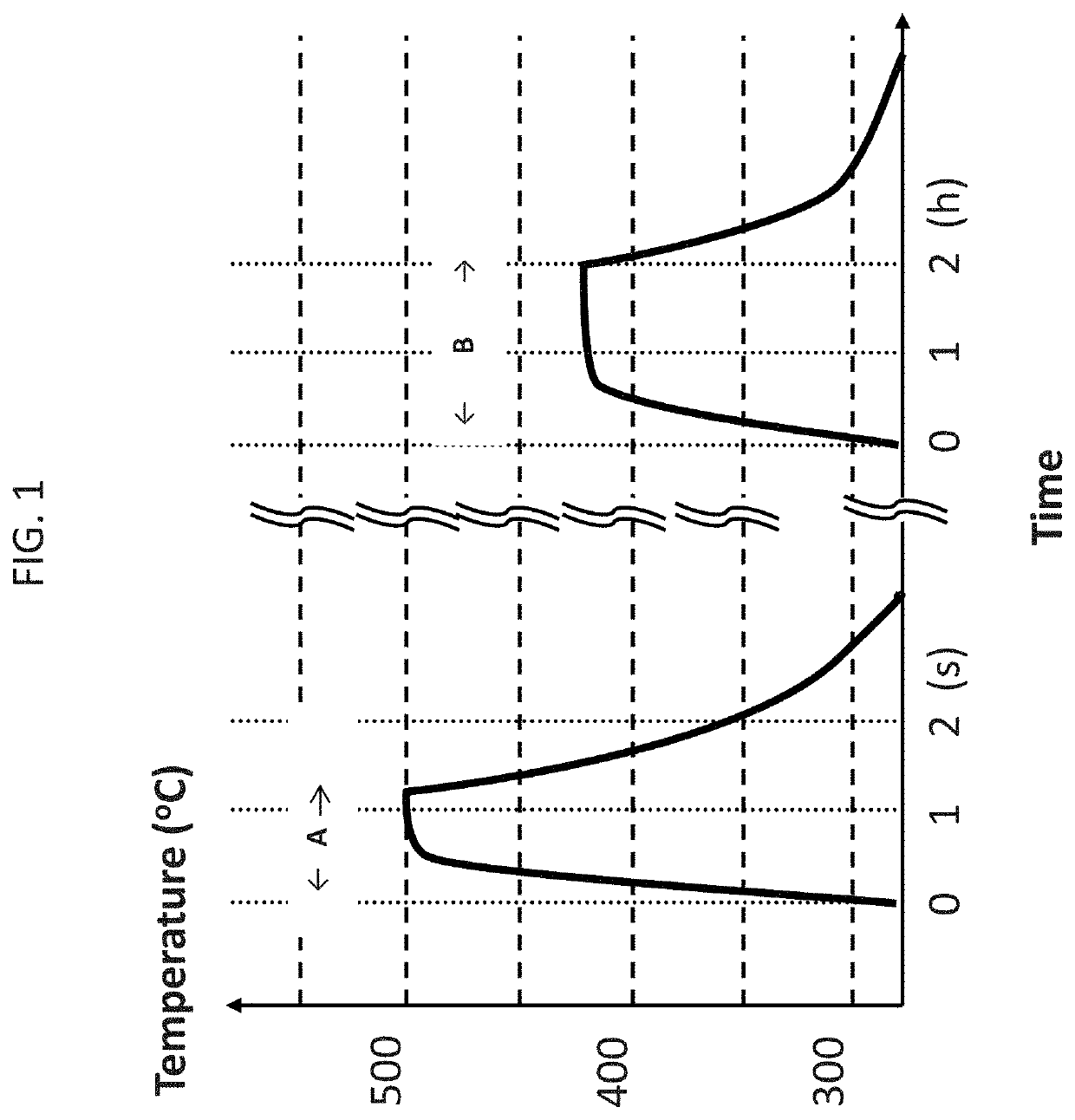
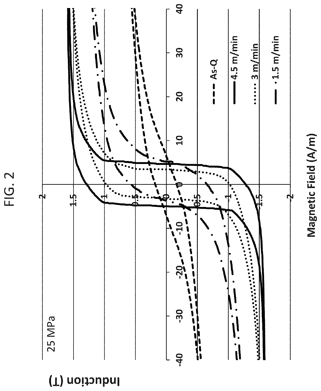
[0060]A rapidly-solidified ribbon having a composition of Fe81Cu1.0Si4B14 was traversed on a 30 cm-long brass plate heated at 490° C. for 3-15 seconds. It took 5-6 seconds for the ribbon to reach the brass-plate temperature of 490° C., resulting in a heating rate of 80-100° C. / sec. The heat-treated ribbon was characterized by a commercial BH loop tracer and the result is given in FIG. 2, where the light solid line corresponds to the BH loop for an as-cast ribbon, and the solid line, dotted line and semi-dotted line correspond to the BH loops for the ribbon tension-annealed with speeds at 4.5 m / min., 3 m / min., and 1.5 m / min., respectively.

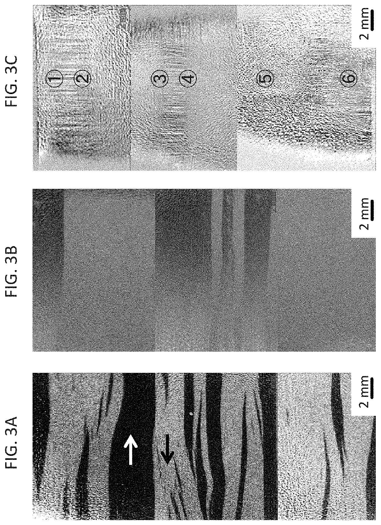
[0061]FIGS. 3A, 3B, and 3C shows the magnetic domains observed on the ribbon of Example 1 by Kerr microscopy. FIGS. 3A, 3B, and 3C are from the flat surface, from the convex and from the concave surface of the ribbon, respectively. As indicated, the direction of the magnetization in the black section points 180° away from the white section. FIGS. 3A...

example 2

[0063]During first heat-treatment of ribbons according to embodiments of the present invention, a radius of curvature developed in the ribbons, although the heat treated ribbon is relatively flat. To determine the range of radius of ribbon curvature, R (mm), in a heat-treated ribbon in which B80 / Bs was greater than 0.90, the B80 / Bs ratio was examined as a function of ribbon radius of curvature which was changed by winding the heat treated ribbon on rounded surface with known radius of curvature. The results are listed in Table 1. The data in Table 1 are summarized by B80 / Bs=0.0028R+0.48. The data in Table 1 is used to design a magnetic core, for example, made from laminated ribbon.

[0064]

TABLE 1Radius of ribbon curvature versus B80 / BsSampleR, Radius of Ribbon Curvature (mm)B80 / Bs1∞0.9822000.9231500.8941000.725580.656250.55712.50.52

[0065]Sample 1 corresponds to the flat ribbon case of FIG. 3A in Example 1, where the magnetization distribution is relatively uniform, resulting in a larg...

example 3

[0067]Strip samples of Fe81Cu1Mo0.2Si4B13.8 alloy ribbon were annealed first with a heating rate of more than 50° C. / s in a heating bath at 470° C. for 15 sec., followed by secondary annealing at 430° C. for 5,400 sec. in a magnetic field of 1.5 kA / m. The first annealing heating rate was found to be as high as 10,000° C. / sec. Strips of the same chemical composition were annealed first with a heating rate of more than 50° C. / s in a heating bath at 481° C. for 8 sec. and with a tension of 3 MPa, followed by secondary annealing at 430° C. for 5,400 sec. with a magnetic field of 1.5 kA / m. Examples of BH loops taken on these strips are shown in FIGS. 5A and 5B.

[0068]FIG. 5A shows BH behavior taken on a Fe81Cu1Mo0.2Si4B13.8 sample annealed first with a heating rate of 50° C. / s in a heating bath at 470° C. for 15 sec. (dotted line), followed by a secondary annealing at 430° C. for 5,400 sec. in a magnetic field of 1.5 kA / m. FIG. 5B shows the BH behavior taken on a sample with the same comp...


PUM

PropertyMeasurementUnit
particle sizesaaaaaaaaaa
radiusaaaaaaaaaa
holding temperatureaaaaaaaaaa

Abstract

A nanocrystalline alloy ribbon has an alloy composition represented by FebalCuxBySizAaXb where 0.6≤x<1.2, 10≤y≤20, 0<z≥10, 10(y+z)24, 0≤a≤10, O≤b≤5, with the balance being Fe and incidental impurities, where A is an optional inclusion of at least one element selected from Ni, Mn, Co, V, Cr, Ti, Zr, Nb, Mo, Hf, Ta and W, and X is an optional inclusion of at least one element selected from Re, Y, Zn, As, In, Sn, and rare earth elements, all numbers being in atomic percent. The ribbon has a local structure having nanocrystals with average particle sizes of less than 40 nm dispersed in an amorphous matrix, the nanocrystals occupying more than 30 volume percent of the ribbon and has a radius of ribbon curvature of at least 200 mm.

Description

BACKGROUND1. Field[0001]Embodiments of the invention relate to a nanocrystalline magnetic alloy having a high saturation induction, low coercivity and low iron-loss, a magnetic component based on the alloy, and a method of heat-treatment thereof.2. Description of Related Art[0002]Crystalline silicon steels, ferrites, cobalt-based amorphous soft magnetic alloys, iron-based amorphous and nanocrystalline alloys have been widely used in magnetic inductors, electrical choke coils, pulse power devices, transformers, motors, generators, electrical current sensors, antenna cores and electromagnetic shielding sheets. Widely used silicon steels are inexpensive and exhibit high saturation induction but are lossy in high frequencies. One of the causes for high magnetic losses is that their coercivity Hc is high, at about 5 A / m. Ferrites have low saturation inductions and therefore magnetically saturate when used in high power magnetic inductors. Cobalt-based amorphous alloys are relatively expe...

Claims


Application Information

Patent Timeline
Patent Type & Authority Patents(United States)
IPC IPC(8): H01F1/147C21D1/18H01F41/02C22C38/02C22C38/16C22C38/12C21D6/00C22C38/00H01F1/153C21D8/12C22C45/02
CPCC22C38/12C21D1/18C21D6/008C21D8/125C21D8/1244C22C38/002C22C38/02C22C38/16H01F1/15333C21D8/1211C21D2201/03C22C45/02H01F1/15308
Inventor OHTA, MOTOKIITO, NAOKI
Owner METGLAS INC
Why Eureka
Try Eureka