Bush cutter

a technology of a bust and a blade is applied in the field of bust cutters, which can solve the problems of limited use environment and limited place for storing the bust, and achieve the effect of easy removal and easy charging operation of the battery

Inactive Publication Date: 2006-11-09
SUBARU CORP
View PDF6 Cites 36 Cited by
  • Summary
  • Abstract
  • Description
  • Claims
  • Application Information

AI Technical Summary

Benefits of technology

[0024] According to the present invention, since the battery to drive the electric motor is attached to the electric motor in a sliding manner, the battery can be taken out from the electric motor and charged as a simple body, whereby the charging operation of the battery can be made easy.
[0025] According to the present invention, since the engine revolution regulator is coupled to the throttle of the engine by the cable, an initial setting of the engine revolution regulator can be made unnecessary when the main body of the bush cutter is attached to the engine. For example, when the main body of the bush cutter is attached to the engine, the regulation of the idling revolution of the engine by the engine revolution regulator is made unnecessary, so that the attaching operation of the engine to the main body of the bush cutter can be made easy.
[0026] According to the present invention, since the motor revolution regulator is coupled to the electric motor by the electric cord, when the main body of the bush cutter is attached to the electric motor, the initial setting of the motor revolution regulator can be made unnecessary. For example, when the electric motor is attached to the main body of the bush cutter, there is no need to couple the motor revolution regulator and the electric motor, so that a connection failure between the motor revolution regulator and the electric motor can be prevented.
[0027] According to the present invention, when the cutter is driven by the electric motor, a cutter having a double edged type blade is attached to the main body of the bush cutter and, by operating the selector switch, the cutter is selectively rotated in any of the forward direction and the reverse direction, so that a blowing direction of mowed grass can be set on the left or right hand. Consequently, for example, when weed sprouting in the slope such as a riverside is mowed off while a worker moves along the riverside, the rotational direction of the cutter can be reversed in performing mowing operations in a left-down state and a right-down state. By so doing, even if the worker continues to perform the mowing operation by turning a worker's body reversely, the mowing operation for continuously blowing off the mowed grass on a lower side of the riverside can be performed.
[0028] According to the present invention, when the mowed grass and the like are entangled into the cutter to lock the cutter while driving the cutter by the electric motor, the electric motor is reversed by operating the selector switch, so that the mowed grass and the like entangled into the cutter can be easily removed.
[0029] According to the present invention, since the selector switch is coupled to the electric motor by the electric cord, when the electric motor is attached to the main body of the bush cutter, the initial setting of the selector switch can be made unnecessary. For example, when the electric motor is attached to the main body of the bush cutter, there is no need to couple the selector switch and the electric motor, so that a connection failure between the selector switch and the electric motor can be prevented.

Problems solved by technology

Thus, although the bush cutter of the electric motor type does not generate louder noises, the place for use thereof is limited in the case of using the commercial power supply and the operation to exchange or charge the battery is required in the case of using the battery.
Although the user of the bush cutter selects either the electric motor type or the engine type according to use environment, the use environment is limited depending on the driving source.

Method used


Image

  • Bush cutter
  • Bush cutter
  • Bush cutter

Examples


Embodiment Construction

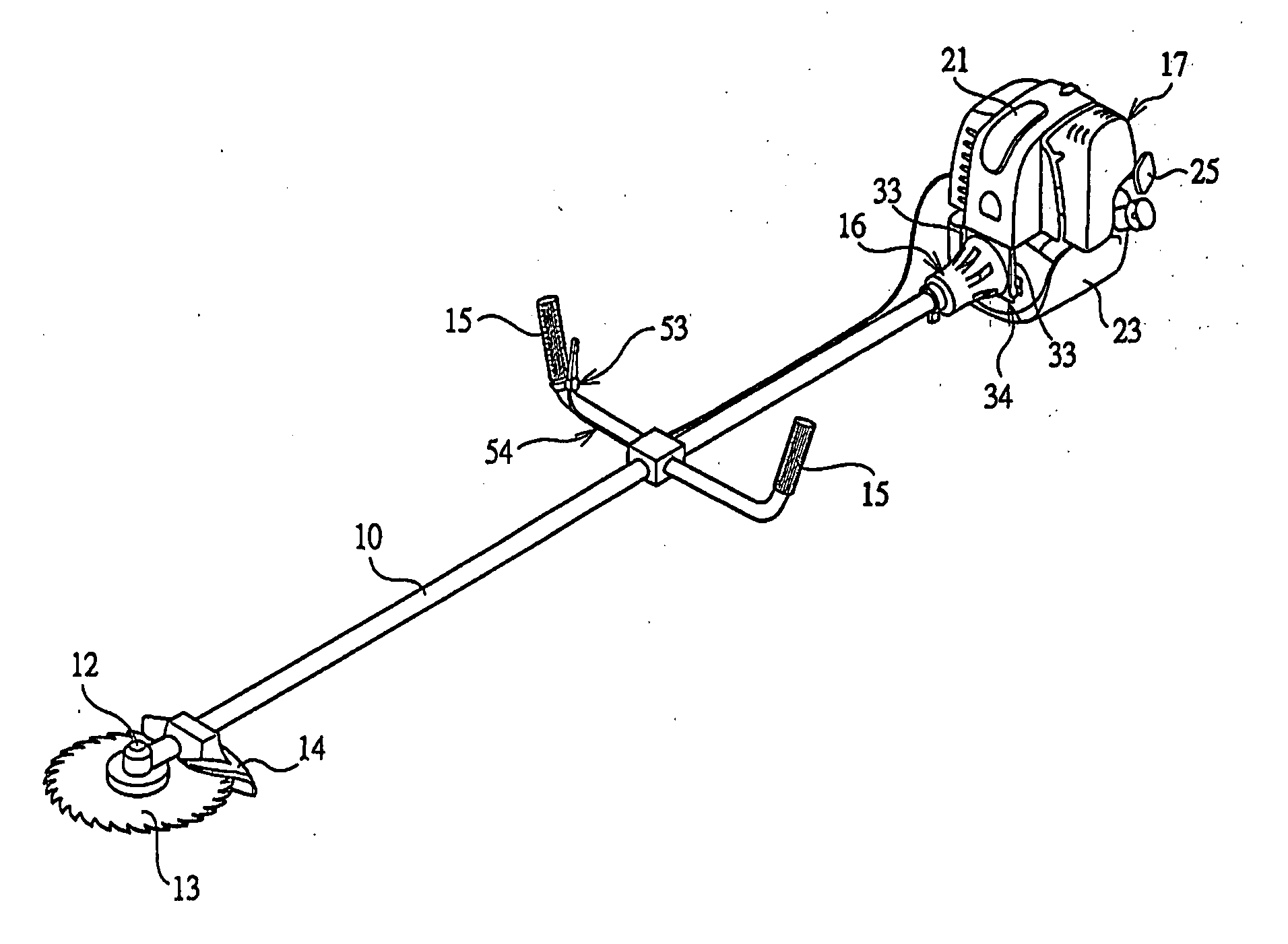
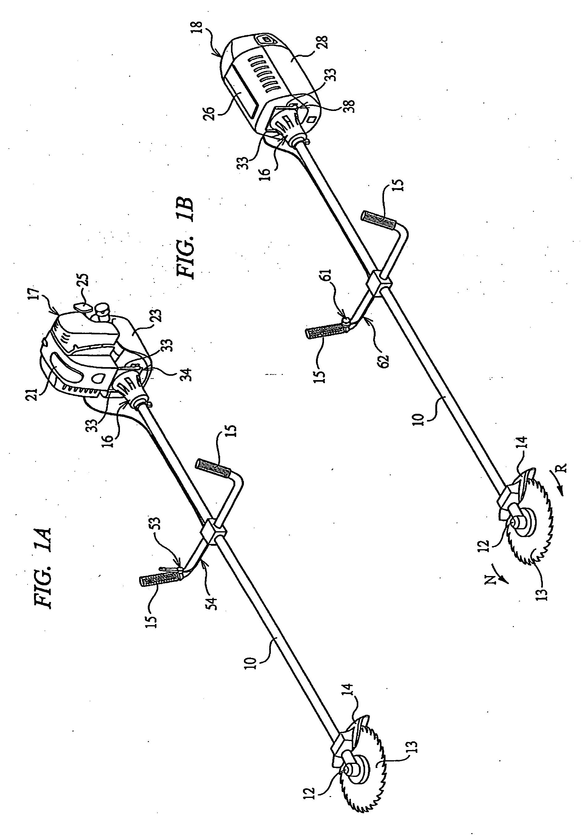
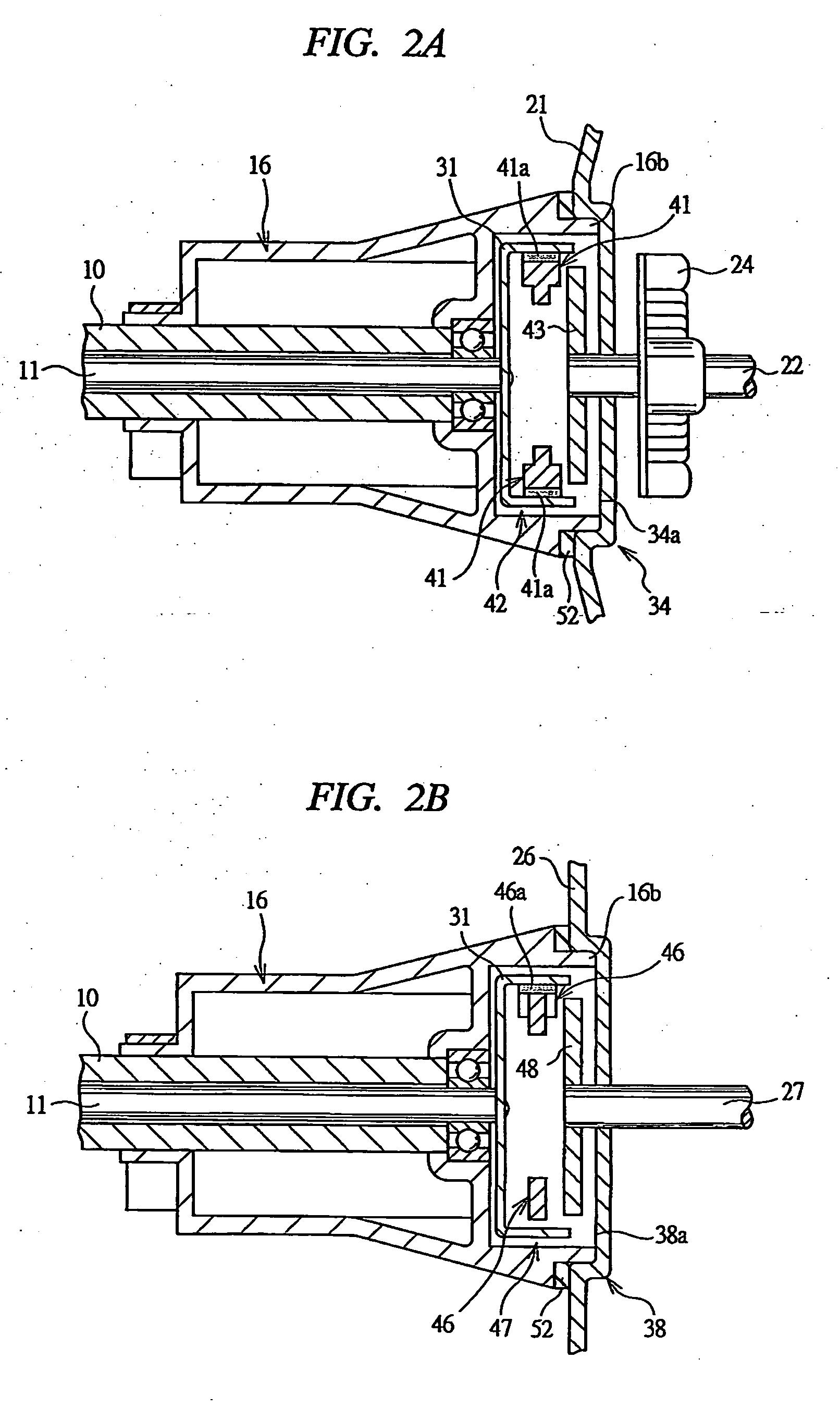
[0058] A bush cutter shown in FIG. 1 is an arm coupling type, and has an operating arm 10 as a main body of the bush cutter. The operating arm 10 is constructed by a hollow bar-shaped member and, in the arm, a driven shaft 11 is rotatably supported as shown in FIGS. 2A and 2B. A holder 12 is mounted on a tip of the operating arm 10 and a disk-shaped metal cutter 13, on whose outer circumferential surface a number of saw-toothed blades are formed, is rotatably mounted to the holder 12. The cutter 13 is coupled to a tip of the driven shaft 11 through a bevel gear pair (omitted in Figures). A cover 14 is mounted on the tip of the operating arm 10 so as to cover a part of the cutter 13, so that safety of the operation is achieved. Note that as the cutter 13, a cutter composed of a plurality of cords extending radially from a rotation center may be used instead of the illustrated disk-shaped metal cutter.

[0059] Two handles 15 are mounted at a longitudinal-directional center portion of t...


PUM


Abstract

A cutter is coupled to a tip of a driven shaft rotatably attached in an operating arm as a main body of a bush cutter, and the other end thereof is provided to a driven side coupling portion selectively coupled with any one of a driving side coupling portion of an engine output shaft and a driving side coupling portion of a motor output shaft. To a driven side joint provided in the other end of the operating arm, any one of an engine output side joint of an engine and an engine output side joint of an electric motor is selectively detachably attached. An engine revolution regulator is connected to the engine through a cable, a motor revolution regulator is connected to the electric motor through an electric cord, and these regulators are detachably attached to a handle of the operating arm.

Description

CROSS-REFERENCE TO RELATED APPLICATION [0001] The entire disclosures of Japanese Patent Applications No. 2005-141396 filed on May 13, 2005, No. 2005-141397 filed on May 13, 2005, No. 2005-136496 filed on May 9, 2005, and No. 2005-138562 filed on May 11, 2005 each including specification, claims, drawings and summary, on each of which the Convention priority of the present application is based, are incorporated herein by reference in its entirety. BACKGROUND OF THE INVENTION [0002] The present invention relates to a bush cutter capable of driving a cutter with any of an engine and an electric motor used as a power source. [0003] In order to mow weeds sprouting in paths between fields or on riversides, bottom weeds of forest lands, meadow grass, or the like, a bush cutter also referred to as a lawn mower is used. The bush cutter includes an arm coupling type in which a cutter is mounted on a tip of an operating arm and a power source is attached to a rear end thereof, and a direct dri...

Claims


Application Information

Patent Timeline
Patent Type & Authority Applications(United States)
IPC IPC(8): B26B7/00
CPCA01D34/90
Inventor SUZUKI, TOSHIYUKIYOSHIDA, KENICHI
Owner SUBARU CORP
Why Eureka
Try Eureka