Spring-assisted paintball loader

a technology of springs and paintballs, applied in the field of ammunition feeding mechanisms, can solve the problems of dry firing of the gun, disruption of the paintball queue, etc., and achieve the effect of avoiding dry firing and steady flow of projectiles

Inactive Publication Date: 2006-11-09
KEE ACTION SPORTS I
View PDF6 Cites 45 Cited by
  • Summary
  • Abstract
  • Description
  • Claims
  • Application Information

AI Technical Summary

Benefits of technology

[0004] The principal and secondary objects of this invention are to assure a steady flow of projectiles into the intake port of a paintball marker, and avoiding dry firing due to gaps in the chain or row of projectiles being dispensed from a hopper or magazine.
[0005] This and other valuable objects are achieved by regulating the feeding of the paintballs to the gun and by maintaining an uninterrupted queue or row of projectiles in line toward the gun intake port According to the invention, a paddlewheel consisting of at least one propelling arm projecting radially from a spinning body in the middle of a circular well located in the lowest region of the projectile magazine or loader is always pushing against the row of paintballs. An exit port in the wall of the well is connected to the gun ammunition intake by a chute or duct. The spinning body is momentarily driven by an electrical motor, and includes a resiliently variable linkage in the form of a spiral spring that remains under partial tension when the motor is de-energized, thus, applying enough pressure through the arm against the row of projectiles being fed to the gun to prevent gaps in the row of the projectiles progressing through the duct.

Problems solved by technology

When the mechanism that propels the paintball toward the shoot or tube leading to the gun intake is started with each pull of the trigger then allowed to stop after a short period, the queue of paintballs may be disrupted when the propelling mechanism stops for lack of feeding pressure behind the last ball in the queue.
Delays and gaps can thus be created, eventually causing dry firing of the gun.

Method used


Image

  • Spring-assisted paintball loader
  • Spring-assisted paintball loader
  • Spring-assisted paintball loader

Examples


Embodiment Construction

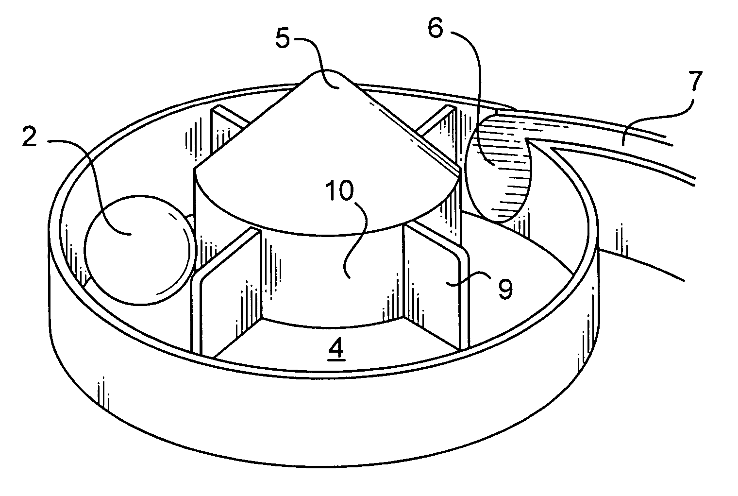
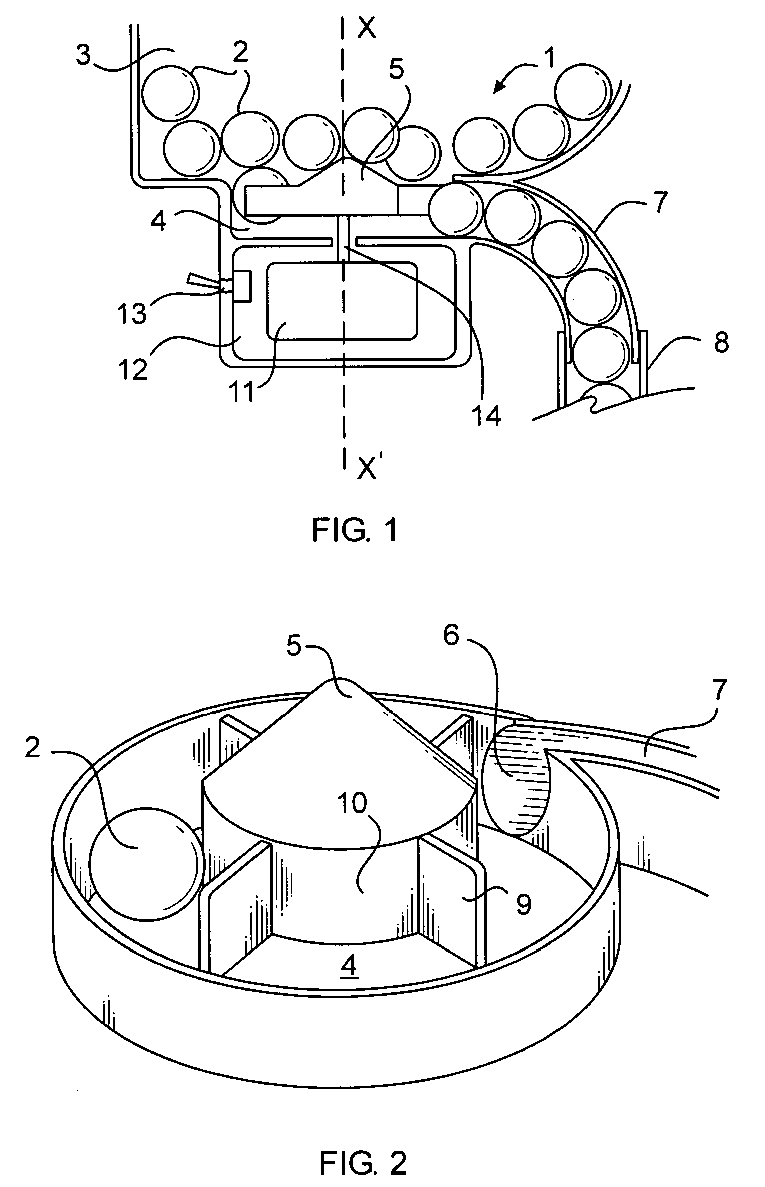
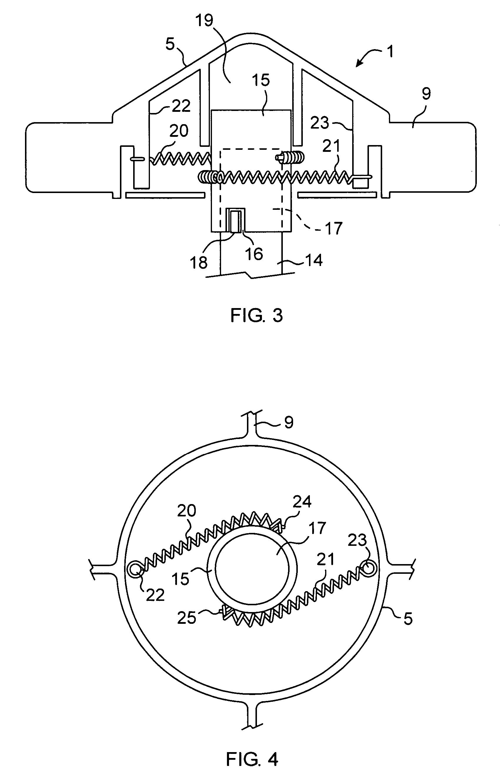
[0013] Referring now to the drawing, there is shown in FIGS. 1-4 a first embodiment 1 of a paintball feeding mechanism according to the invention.

[0014] As paintballs 2 held in the magazine 3 drop into a well 4 in a lower region of the magazine, they are contacted by a spinning body in the form of a spool 5 and directed toward the inlet 6 of a duct 7 leading to the ammunition intake port 8 of a paintball marker or gun. A series of vanes or paddles 9 projecting radially and outwardly from the peripheral, outer wall 10 of the spool act as impelling arms for the paintballs 2. An electrical motor 11 positioned in a housing 12 immediately under the magazine well 4 can be energized and started, then stopped by means of a toggle switch 13. Alternately, as commonly found in certain paintball markers, the start of the motor can be initialized by the trigger mechanism and automatically stopped after a short period of time, or upon release of the trigger. The axle 14 of the motor engages the ...


PUM


Abstract

A mechanism for feeding uniformly-sized spherical projectiles such as paintballs into a gun adapted to shoot said projectiles is positioned in a lower region of a paintball-holding magazine, and includes a spinning body in the form of a spool from the peripheral side of which project radial arms shaped and dimensioned to urge projectiles toward a duct leading to the ammunition intake port of the gun. The spool is driven by a switchable electrical motor. In order to avoid gaps into the row of paintballs that are urged toward the ammunition intake port when the motor is not running which could result in dry firing, a resiliently variable linkage between the propelling arms is provided by a spiral spring or a pair of stretchable coil springs.

Description

FIELD OF THE INVENTION [0001] This invention relates to ammunition feeding mechanisms and more specifically to mechanisms for feeding uniformly-sized spherical projectiles such as paintballs into a gun. BACKGROUND OF THE INVENTION [0002] The firing rate of most recent versions of paintball markers (also called paintball gun) sometimes exceeds the rate at which projectiles can be fed into the breech intake port. Accordingly, when feeding paintballs from a hopper or magazine, it is critical not to allow any delay or gap in the chain of projectiles moving toward the intake port of the marker. When the mechanism that propels the paintball toward the shoot or tube leading to the gun intake is started with each pull of the trigger then allowed to stop after a short period, the queue of paintballs may be disrupted when the propelling mechanism stops for lack of feeding pressure behind the last ball in the queue. Delays and gaps can thus be created, eventually causing dry firing of the gun....

Claims


Application Information

Patent Timeline
Patent Type & Authority Applications(United States)
IPC IPC(8): F41F1/00
CPCF41B11/53F41A9/02
Inventor BROERSMA, LESTER
Owner KEE ACTION SPORTS I
Why Eureka
Try Eureka