Backing paper control

Inactive Publication Date: 2006-11-09
MARKEM IMAJE AB
View PDF3 Cites 12 Cited by
  • Summary
  • Abstract
  • Description
  • Claims
  • Application Information

AI Technical Summary

Benefits of technology

[0008] The invention provides a simple and reliable solution for making the mounting of backing paper with labels attac

Problems solved by technology

A problem with this type of construction is that when mounting the backing paper, it has to be mounted along a long path formed by all the dancing arms and other components controlling the path of the backing paper the

Method used


Image

  • Backing paper control
  • Backing paper control
  • Backing paper control

Examples


Example

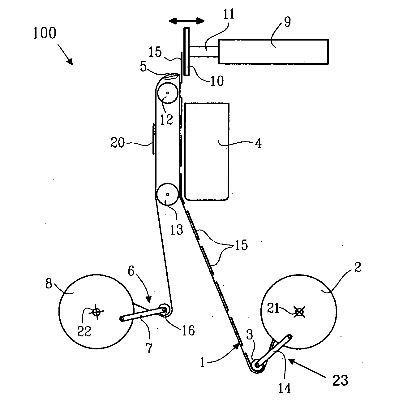
[0045]FIG. 1 illustrates a label application system 100 for application of labels to an object. The labels are stored on a protective backing paper 1 mounted on a storage roll 2 (or reel) rotatable around an axis 21. The backing paper 1 is transferred to a printing device 4 guided by a guiding roll or wheel 3 mounted on an arm 14 together form a first dancing arm 23. The backing paper 1 passes by an edge 5 providing a pressure on a back side of the backing paper 1 since the backing paper 1 is directly turned and drawn back downwards again as seen in FIG. 1. Due to of the back pressure applied to the backing paper 1, the label loosens from the backing paper 1 and continues to travel to a label applicator head 10 and adheres to the label applicator head 10, e.g. by a suction or adhesive force provided by a suction device. The suction device reduces pressure in distribution channels located on the applicator head 10 on the same side as the label will adhere to. Other suction force gene...


PUM

PropertyMeasurementUnit
Forceaaaaaaaaaa
Radiusaaaaaaaaaa
Tensionaaaaaaaaaa

Abstract

A system, method and computer program for removing faulty RFID tagged labels from a label applicator system wherein a RFID testing device detects faulty RFID tag whereby a tension on a label backing paper is reduced so as to increase a radius at a position of transferal of the labels from the label backing paper to a label applicator head. The increase in radius has the effect that the label is not transferred to the label applicator head but instead remains on the backing paper and thus will not be applied to a object to be labeled.

Description

PRIORITY CLAIM [0001] This application claims priority to Provisional Application No. 60 / 684,555, filed May 9, 2005, the contents of which is incorporated herein in its entirety.FIELD OF THE INVENTION [0002] The present invention relates to a device and system for controlling the motion of backing paper in a labeling application device, and in particular to a device allowing for controlled mounting of backing paper and rejecting of faulty labels. BACKGROUND OF THE INVENTION [0003] In labeling application devices labels are situated on a backing paper which in turn is mounted on for instance a storage roll or reel at one end and on a collecting roll at the other end. There between one or several dancing arms keep the backing paper stretched. A problem with this type of construction is that when mounting the backing paper, it has to be mounted along a long path formed by all the dancing arms and other components controlling the path of the backing paper thereby leading to a waste of b...

Claims


Application Information

Patent Timeline
IPC IPC(8): B65C9/42B32B41/00
CPCB65C9/1884Y10T156/1707B65C2009/0093B65C2009/404B65H29/62B65H37/002B65H2511/40B65H2515/31B65H2515/84B65H2557/13B65H2701/194B65C2009/0003B65H2220/02B65H2220/01
Inventor DIJKSTRA, GERARD
Owner MARKEM IMAJE AB
Why Eureka
Try Eureka