Analog watch fiber optic image guide

an image guide and analog watch technology, applied in the field of analog watch fiber optic image guides, can solve the problems of not being considered commercially feasible, unable to meet the requirements of the application of fiber optic faceplates in combination with information displays, and offering little to no significant improvement in image quality that might justify the added cost of external fiber optic faceplates. , to achieve the effect of reducing light refraction, ensuring water resistance, and adding protection to the underlying information display

Inactive Publication Date: 2006-11-09
BREWER DONALD R
View PDF18 Cites 10 Cited by
  • Summary
  • Abstract
  • Description
  • Claims
  • Application Information

AI Technical Summary

Benefits of technology

[0031] One or more embodiments of the present invention might be used in wrist watches, particularly digital wrist watches. One feature of interest in such wrist watches is the provision of a minimal amount of water resistance, with most watches possessing water resistance of several atmospheres from 3 ATM, 5 ATM, and as high as 10 ATM. Some embodiments of the present invention discussed herein will include construction techniques for preferably integrating the fiber image guide with the watch case to maintain levels of water resistance. Also discussed herein are embodiments that provide additional protection of the underlying information display by modif

Problems solved by technology

Although discussed in the two patents to Hubby, Jr. filed approximately 15 years ago, fiber optic faceplates in combination with information displays have not been accepted in the market to any significant degree.
Although the image quality of liquid crystal displays can be improved as discussed in the patents to Hubby, Jr., the method discussed therein (which often involves replacing the top glass substrate layer with a fiber optic faceplate) is generally not considered commercially feasible due to the production techniques and materials.
As taught, however, they offer little to no significant improvement in image quality that might justify the added cost of the external fiber optic faceplate.
As discussed

Method used


Image

  • Analog watch fiber optic image guide
  • Analog watch fiber optic image guide
  • Analog watch fiber optic image guide

Examples


Embodiment Construction

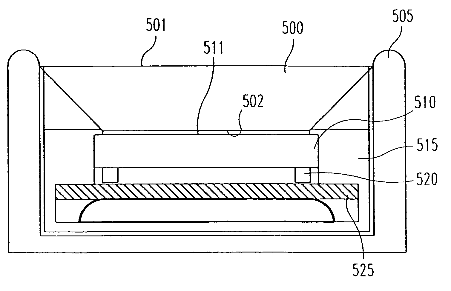
[0052] It should be understood that the term information display as used herein is intended to encompass a wide variety of displays including, but not limited to, liquid crystal displays (twisted nematic, super twisted, active matrix) organic light emitting diode (OLED) displays, and dynamic scattering liquid crystal displays. The term information display is also intended to encompass other displays in commercial use or under development that could be utilized in one or more embodiments of the present invention, such as liquid crystal on silicon (LCOS). Those skilled in the art will also recognize that most, if not all, of the embodiments disclosed herein involving the use of a fiber optic image guide could be utilized with any of the wide variety of information display technologies just discussed. It should be understood that for both liquid crystal displays and OLEDs, continued development is ongoing to produce displays with plastic or polymer outer substrates. This continued deve...


PUM


Abstract

An analog watch includes an analog movement capable of providing at least time information indicated by at least two movement hands positioned over a watch dial. The analog watch further includes a fiber optic image guide having a taper extending from a bottom surface to a top surface. The bottom surface of the fiber optic image guide is optically coupled to the watch dial. The taper of the fiber optic image guide extends from the bottom surface to the top surface in such a manner that an image present at the watch dial is magnified for viewing at the top surface of the fiber optic image guide.

Description

[0001] This application claims the benefit of U.S. Provisional Application Ser. No. 60 / 677,506 entitled “Watch Fiber Optic Image Guide” that was filed on May 4, 2005 and also claims the benefit of U.S. application Ser. No. 11 / 139,329 entitled “Watch Fiber Optic Image Guide” that was filed on May 27, 2005.BACKGROUND OF THE INVENTION [0002] Currently there is a wide assortment of consumer electronic devices such as mobile phones, MP3 players, and wrist watches (particularly digital wrist watches) that include an informational display, such as a liquid crystal display (“LCD”), as the main visual interface to the device. In many such product applications the information display is a prominent design element. The proliferation of inexpensive consumer electronics has commoditized the appearance of a typical black on grey liquid crystal display, and even color active matrix displays are now found in a wide assortment of mobile phones. Many of these types of consumer electronic devices are ...

Claims


Application Information

Patent Timeline
IPC IPC(8): G04C19/00
CPCG02B6/06G02B6/325G04G9/00G04C17/00G02B6/4248
Inventor BREWER, DONALD R.
Owner BREWER DONALD R
Why Eureka
Try Eureka