MIMO PGRC system and method

Active Publication Date: 2006-11-09
TEXAS INSTR INC
12 Cites 113 Cited by

AI-Extracted Technical Summary

Problems solved by technology

These interference signals degrade the intended data signal at the user equipment.
Thus, when the transmitted communication arrives at the receiver, it has been affected by the channel effect as well as interference signals.
Consequently, the originally-transmitted data is more difficult to decipher.
C...

Benefits of technology

[0013] In a second preferred embodiment, a wireless receiver receives a plurality of signals from a plurality of remote transmit antennas. The wireless receiver detects a first signal from a first group of the plurality of remote transmit antennas. Signals in the first group are encoded at a first code rate. The wireless receiver receives a second signal from a second gro...

Abstract

A method of transmitting a wireless signal (FIGS. 3A-3C) is disclosed. A data stream is divided (306) into a first data stream and a second data stream. The first data stream is encoded (300) at a first data rate. The second data stream is encoded (320) at a second data rate different from the first data rate. A first part of the encoded first data stream is transmitted from a first transmit antenna (308). A second part of the encoded first data stream is transmitted from a second transmit antenna (312).

Application Domain

Technology Topic

Image

  • MIMO PGRC system and method
  • MIMO PGRC system and method
  • MIMO PGRC system and method

Examples

  • Experimental program(1)

Example

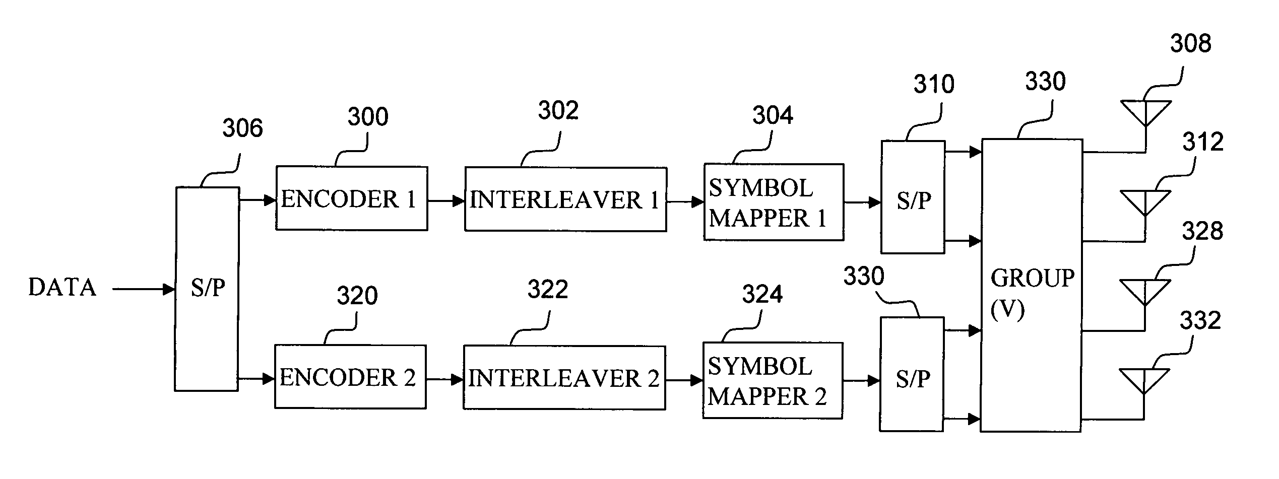
[0025] The preferred embodiments of the present invention provide circuit simplification for a wireless communication system. The wireless communication system preferably provides for the Long Term Evolution of High-Speed Downlink Packet Access (HSDPA) and Multiple-input Multiple-output (MIMO) as will be explained in detail. A simplified block diagram of a wireless transmitter of the present invention for such a system is shown in FIG. 3A. The wireless transmitter includes two separate modulation code schemes (MCS) and four transmit antennas. Each MCS preferably includes an encoder, an interleaver, and a symbol mapper.
[0026] The wireless transmitter of FIG. 3A receives an input data stream from a baseband processor (not shown). This data stream may include pilot signals, control signals, and data signals for synchronization and control of remote wireless user equipment (UE). The data stream is divided into first and second data streams by serial-to-parallel circuit 306. Both first and second data streams are separately encoded based on channel quality information (CQI). The particular code may be a low density parity code, turbo code, Hamming code, Reed Solomon code, or other code as is known in the art. Moreover, the particular code may be different for each encoder 300 and 320. The CQI corresponding to each encoder 300 and 320 is preferably fed back from a remote UE in a previous communication. A particular code rate for each encoder is selected to reduce data errors and minimize retransmission of data. In general, a code rate of N/M indicates that N input data bits produce M encoded output data bits. In practical wireless communication systems, the code rate may vary from ⅛ for low CQI to ⅚ for high CQI. The first data stream is encoded at a first data rate by encoder 300. The second data stream is encoded at a second data rate by encoder 320. Interleavers 302 and 322 interleave their respective encoded data streams which are then applied to respective symbol mappers 304 and 324. The symbol mappers convert the interleaved data streams to respective symbol constellations. These symbol constellations may be, for example, QPSK (2 bit), 16-QAM (4 bit), or 64-QAM (16 bit). An appropriate symbol constellation is preferably selected in response to the CQI. For a low CQI, the symbol mapper may produce a QPSK symbol. Alternatively, for a high CQI, the symbol mapper may produce a 64-QAM symbol.
[0027] Data symbols from symbol mapper 304 are applied to serial-to-parallel circuit 310 to produce two parallel symbol streams. Likewise, data symbols from symbol mapper 324 are applied to serial-to-parallel circuit 330 to produce two parallel symbol streams. These four parallel symbol streams are applied to group circuit 330. Group circuit 330 then applies the parallel symbol streams having the highest data rate to the two best transmit antennas having the highest CQI. Group circuit 330 applies the remaining parallel symbol streams having the lowest data rate to the remaining two transmit antennas having the lowest CQI. The MCS with maximum data throughput or code rate, therefore, is applied to the transmit antennas having the best CQI. The MCS with a lesser data throughput or code rate is applied to the transmit antennas having a lesser CQI. Alternative grouping schemes, such as strong and weak transmit antennas, necessarily limit data throughput of each MCS to that of the weakest transmit antenna having the minimum CQI. In a preferred embodiment of the present invention, group circuit 330 also pre-codes the parallel symbol streams. Pre-coding preferably multiplies each symbol stream by a matrix V to correct or counteract the anticipated channel gain and rotation prior to transmission. The matrix V can be unitary or non-unitary. Here, a square matrix is unitary when the conjugate transpose VH is equal to the matrix inverse V−1. When V is unitary, V may be generated using Givens or Householder constructions. In a preferred embodiment of the present invention, matrix V of group circuit 330 is unitary. The anticipated channel rotation or an indication of the chosen matrix V is preferably fed back from a remote UE together with CQI. The present invention, therefore, advantageously tailors each MCS code rate and symbol mapping scheme to the CQI for respective transmit antennas. Moreover, circuit complexity is reduced by half as compared to 4-antenna PARC circuits of the prior art while providing approximately the same performance as will be explained in detail.
[0028] Turning now to FIG. 3B, there is another embodiment of a transmitter of the present invention. Like numbered circuit blocks perform substantially the same functions as previously described with regard to the transmitter of FIG. 3A. However, interleaved data streams from blocks 302 and 322 are applied directly to serial-to-parallel circuits 340 and 342, respectively. Each serial-to-parallel circuit produces two parallel interleaved data streams. The two parallel data streams from serial-to-parallel circuit 340 are applied to symbol mapper circuits 350 and 352. Likewise, the two parallel data streams from serial-to-parallel circuit 342 are applied to symbol mapper circuits 354 and 356. Each of symbol mapper circuits 350-356 may produce any combination of symbol constellations. Thus, each MCS of FIG. 3B may advantageously produce two different code rates as well as two different symbol constellations for each respective code rate. The additional symbol mapper circuits, therefore, advantageously provide a finer resolution of data throughput in response to the CQI than the circuit of FIG. 3A for slightly greater circuit complexity.
[0029] Referring now to FIG. 3C, there is another embodiment of the present invention. Like numbered circuit blocks perform similar functions as previously described with regard to the transmitter of FIG. 3B. Orthogonal frequency division multiplex (OFDM) transmitters 360-366 are added to transmit OFDM symbols from respective transmit antennas 308, 312, 328, and 332. Symbol mapper circuits 350-356 receive respective data streams from serial-to-parallel converter circuits 340 and 342 and produce frequency domain data symbols. Group circuit 330 then applies the frequency domain data symbols having the highest data rate to the OFDM transmitters corresponding to the two best transmit antennas having the highest CQI. The remaining frequency domain data symbols having the lowest data rate are applied to the remaining OFDM transmitters corresponding to the two transmit antennas having the lowest CQI. An inverse fast Fourier transform (IFFT) converts the frequency domain data symbols into time domain waveforms. The IFFT structure allows the frequency tones to be orthogonal. The OFDM symbols are upconverted to RF and transmitted by respective OFDM transmitters 360-366 on multiple carriers that are spaced apart to provide orthogonality. The present invention, therefore, advantageously provides two MCS data rates and four selectable symbol mapper circuits for maximum data throughput. Furthermore, the present invention is compatible with OFDM transmission.
[0030] Referring now to FIG. 5, there is yet another embodiment of the present invention adapted to multiuser transmission. The wireless transmitter of FIG. 5 receives multiple data input streams from user buffers 540-544. Data from these input buffers is applied to serial-to-parallel circuit 506 and divided into first and second data streams. The first data stream is applied to the upper MCS including encoder 500, interleaver 502, and symbol mapper 504. The second data stream is applied to the lower MCS including encoder 520, interleaver 522, and symbol mapper 524. Both first and second data streams are separately encoded based on channel quality information (CQI) as previously described with regard to FIG. 3A. For the multiuser case, however, a single MCS may be assigned to a user with higher data throughput requirements. Other users with lower throughput requirements may be assigned to the remaining MCS. For example, UE 1 buffer 504 may be sending High-Speed Downlink Packet Access (HSDPA). UE 2542 and UE 3544 may be sending voice, stock quotes, or other low speed data. UE 1 buffer 540 is preferably assigned to the upper MCS, and UE 2542 and UE 3544 buffers are assigned to the lower MCS. Each encoder is 500 and 520 selects a code rate compatible with the CQI. Interleavers 502 and 522 interleave their respective encoded data streams which are then applied to respective symbol mappers 504 and 524. The symbol mappers convert the interleaved data streams to respective symbol constellations. These symbol constellations may be, for example, QPSK (2 bit), 16-QAM (16 bit), or 64-QAM (64 bit). An appropriate symbol constellation is preferably selected in response to the CQI as previously described with respect to FIG. 3A.
[0031] Data symbols from symbol mappers 504 and 524 are applied to serial-to-parallel circuits 510 and 530, respectively, to produce four parallel symbol streams. These four parallel symbol streams are applied to group circuit 530. Group circuit 530 then applies the parallel symbol streams having the highest data rate to the two best transmit antennas having the highest CQI. Group circuit 530 applies the remaining parallel symbol streams having the lowest data rate to the remaining two transmit antennas having the lowest CQI. The MCS with maximum data throughput or code rate, therefore, is applied to the transmit antennas having the best CQI. The MCS with a lesser data throughput or code rate is applied to the transmit antennas having a lesser CQI. In a preferred embodiment of the present invention, group circuit 530 also pre-codes the parallel symbol streams as previously described. Pre-coding multiplies each symbol stream by a matrix V to correct or counteract the anticipated channel gain and rotation prior to transmission. The matrix V can be unitary or non-unitary. When V is unitary, V may be generated using Givens or Householder constructions. In a preferred embodiment of the present invention, matrix V of group circuit 330 is unitary. The anticipated channel rotation or an indication of the chosen matrix V is preferably fed back from a remote UE together with CQI. The present invention, therefore, advantageously tailors each MCS code rate and symbol mapping scheme to the CQI for respective transmit antennas. MCS allocation is determined by data throughput requirements for each UE. Moreover, circuit complexity is reduced by half as compared to 4-antenna PARC circuits of the prior art while providing approximately the same performance.
[0032] Referring to FIG. 6A, there is a simplified block diagram of a wireless receiver of the present invention. Inventive features of the previously described transmitters of the present invention are included in the receiver for compatibility. Antennas 630-636 receive signals from a remote transmitter. In a preferred embodiment, there are two, four, or more antennas 630-636. Received signals at each antenna 630-636 include signals from each transmit antenna of a remote transmitter. For example, antenna 630 receives signals from transmit antennas 308-332 (FIG. 3A) in a single user environment. Antenna 630 also receives signals from transmit antennas 508-532 (FIG. 5) in a multiuser environment. However, in the multiuser environment, signals from transmit antenna 508 may be intended for the receiver of FIG. 6A while signals from transmit antennas 512-532 may be interference. Received signals from antennas 630-636 are applied to Mean Minimum Square Error (MMSE) detection circuit 602. The MMSE detection circuit detects user data streams from receive antennas 630-636. Alternative detection circuits utilizing match filter, zero forcing, or least square algorithms as are known in the art may also be used in lieu of MMSE detection. For CDMA applications, the received signals may be despread with user-specific spreading codes. Circuit 614 extracts pilot signals from these user data streams. These pilot signals may have a power boost relative to data signals. The extracted pilot signals are applied to circuit 610 to compute an effective channel matrix representing the channel effect between the receiver and remote transmitter. The outputs of the MMSE detection circuit 602 are applied to the multi-antenna processing circuit 604 and corrected by the effective channel matrix from circuit 610. Different types of multi-antenna processing can be used such as linear, decision feedback, or maximum likelihood. These signals are subsequently converted to a serial data stream by parallel-to-serial converter 606. The serial data stream is then demapped, deinterleaved, and, decoded in circuit 608 and applied to a baseband processor (not shown). An optional feedback loop 612 from circuit 608 to circuit 604 allows a decision feedback operation which can improve the estimation of data bits. The decision feedback operation may include successive interference cancellation (SIC) wherein each detected signal is successively removed from the composite received signal.
[0033] Circuit 608 also calculates a group SINR from the received signal which is subsequently retransmitted to the remote transmitter as a CQI. The group SINR corresponds to a particular transmitter MCS that produced the intended user signal. In a single user environment, the receiver preferably reports an SINR for each MCS of the transmitter of FIG. 3A. By way of contrast, MIMO receivers of the prior art are required to report a separate SINR for each transmit antenna of a PARC transmitter. Thus, the present invention advantageously reduces the SINR reporting overhead by half in a single user environment. Alternatively, for a multiuser environment, the receiver of FIG. 6A reports a single SINR for the remote transmitter MCS producing the intended user data stream.
[0034] Referring now to FIG. 6B, there is a simplified block diagram of another embodiment of a wireless receiver of the present invention. Like numbered circuit blocks perform substantially the same functions as previously described with regard to the receiver of FIG. 6A. Antennas 630-636 receive signals from a remote transmitter. In a preferred embodiment, there are two, four, or more antennas 630-636. Received signals at each antenna 630-636 include signals from each transmit antenna of a remote transmitter as previously described. These received signals are applied to respective OFDM receiver circuits 620-626. The OFDM circuits perform an FFT on each OFDM data stream to convert received signals to a stream of OFDM signals or tones in the frequency domain. The OFDM tones are applied to Mean Minimum Square Error (MMSE) detection circuit 602. As with the circuit of FIG. 6A, alternative detection circuits utilizing match filter, zero forcing, or least square algorithms as are known in the art may also be used in lieu of MMSE detection. The MMSE detection circuit detects user data streams from OFDM receivers 620-626. Circuit 614 extracts pilot tones from these user data streams. The extracted pilot tones are applied to circuit 610 to compute the effective channel matrix between the receiver and remote transmitter. The outputs of the MMSE detection circuit 602 are applied to the multi-antenna processing circuit 604 and corrected by the effective channel matrix from circuit 610. Different types of multi-antenna processing can be used such as linear, decision feedback, or maximum likelihood. These signals are subsequently converted to a serial data stream by parallel-to-serial converter 606. The serial data stream is then demapped, deinterleaved, and, decoded in circuit 608 and applied to a baseband processor. As previously described, an optional feedback loop 612 from circuit 608 to circuit 604 allows a decision feedback operation which can improve the estimation of data bits. The decision feedback operation may include successive interference cancellation (SIC) wherein each detected signal is successively removed from the composite received signal.
[0035] Referring now to FIGS. 7A and 7B there are simulations of the present invention and circuits of the prior art. The simulation of FIG. 7A is based on a spatial correlation value of zero (ρ=0). This represents an ideal case of orthogonal signals where a receiver correctly identifies each signal from each transmit antenna. The simulation of FIG. 7A is based on a spatial correlation value of zero (ρ=0). By way of comparison, the simulation of FIG. 7B represents a worst case where received signals correlate 50% of the time (ρ=0.5). Both simulations assume a 10 user scheduler maximum carrier-to-interference (MCI) ratio, a low doppler rate, and 5 MHz channel bandwidth for OFDM transmission with iterative MMSE detection. The vertical axis of each simulation is throughput in units of bits-per-second/Hz/sector. The horizontal axis is a ratio of received signal power (IOR) to total channel power (IOC) in dB. This is comparable to a SINR as previously described. In view of the foregoing, only the curves of FIG. 7A will be described in detail.
[0036] The simulation of FIG. 7A includes eight curves. Numbers in the legend indicate a number of transmit and receive antennas, respectively, in the communication system. For example, the 1×1 curve indicates a prior art communication system with a single transmit antenna and a single receive antenna. This curve establishes a baseline for comparison of performance of the present invention with circuits of the prior art. The 1×1 curve increases throughput from 0 to 4.5 with IOR/IOC increasing from −10 dB to 15 dB. No substantial improvement is seen for values of IOR/IOC above 15 dB for this curve or any of the other seven curves. A second group of 2×2 curves shows a significant improvement over the 1×1 curve. This second group includes V-BLAST (2×2 VBLAST), single user PARC (2×2 SU-PARC), and multiuser PARC (2×2 MU-PARC). The second group approximately doubles the throughput of the 1×1 system to 9.0 at 15 dB. The multiuser (2×2 MU-PARC) shows a slight advantage in throughput over the other two systems. A third group of 4×4 curves shows a significant improvement over the 1×1 curve and the second group of 2×2 curves. This third group includes V-BLAST (4×4 VBLAST), single user PGRC (4×4 SU-PGRC), multiuser PARC (4×4 MU-PARC), and multiuser PGRC (4×4 MU-PGRC). The third group approximately doubles the throughput of the 2×2 system to 18.0 at 15 dB. The multiuser (4×4 MU-PGRC) shows a consistent advantage in throughput over the single user (4×4 SU-PGRC) system. However, performance of the multiuser PGRC (4×4 MU-PGRC) system of the present invention is virtually identically to the multiuser PARC (4×4 MU-PARC) system of the prior art throughout the simulation range. Thus, the present invention greatly simplifies circuit complexity and reduces uplink SINR reporting relative to PARC systems of the prior art while offering virtually identical throughput.
[0037] Still further, while numerous examples have thus been provided, one skilled in the art should recognize that various modifications, substitutions, or alterations may be made to the described embodiments while still falling with the inventive scope as defined by the following claims. For example, the present invention may be applied to any number of antennas greater than four. When 6 antennas are present, they may be grouped into 3 groups of 2 antennas each or 2 groups of 3 antennas each. Likewise, when 8 antennas are present, they may be grouped into 2 groups of 4 antennas each or 4 groups of 2 antennas each. Other combinations will be readily apparent to one of ordinary skill in the art having access to the instant specification.

PUM

no PUM

Description & Claims & Application Information

We can also present the details of the Description, Claims and Application information to help users get a comprehensive understanding of the technical details of the patent, such as background art, summary of invention, brief description of drawings, description of embodiments, and other original content. On the other hand, users can also determine the specific scope of protection of the technology through the list of claims; as well as understand the changes in the life cycle of the technology with the presentation of the patent timeline. Login to view more.

Similar technology patents

Classification and recommendation of technical efficacy words

Why Eureka
Try Eureka