Master-slave synchronization communication method
a communication method and masterslave technology, applied in the field of communication systems, can solve the problems of jitter at a synchronization point, inability to modify, fixed natural period, etc., and achieve the effect of preparing to implement desired master/slave synchronization communications
- Summary
- Abstract
- Description
- Claims
- Application Information
AI Technical Summary
Benefits of technology
Problems solved by technology
Method used
Image
Examples
first embodiment
[0058] First of all, feature names and signal names specified in the IEEE1394 Standard that appear in the following description will be described. As shown in FIG. 5, the CYCLE_TIME resister is composed of a cycle_offset part, a cycle_count part and a second_count part. The cycle_offset part counts a clock of 24.576 Hz in each station. When the count reaches 3072, the cycle_offset part outputs a carry every 125 μs of a natural period. The cycle_count part counts carries from the cycle_offset part. When the count reaches 8000, the cycle_offset part outputs a carry every 1 s. Cycle_sync is a synchronization signal issued every 125 μs of a natural period.
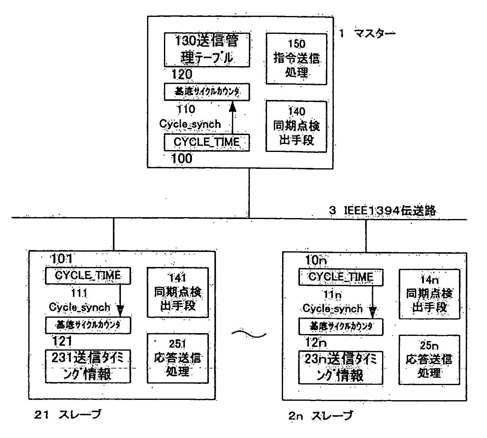
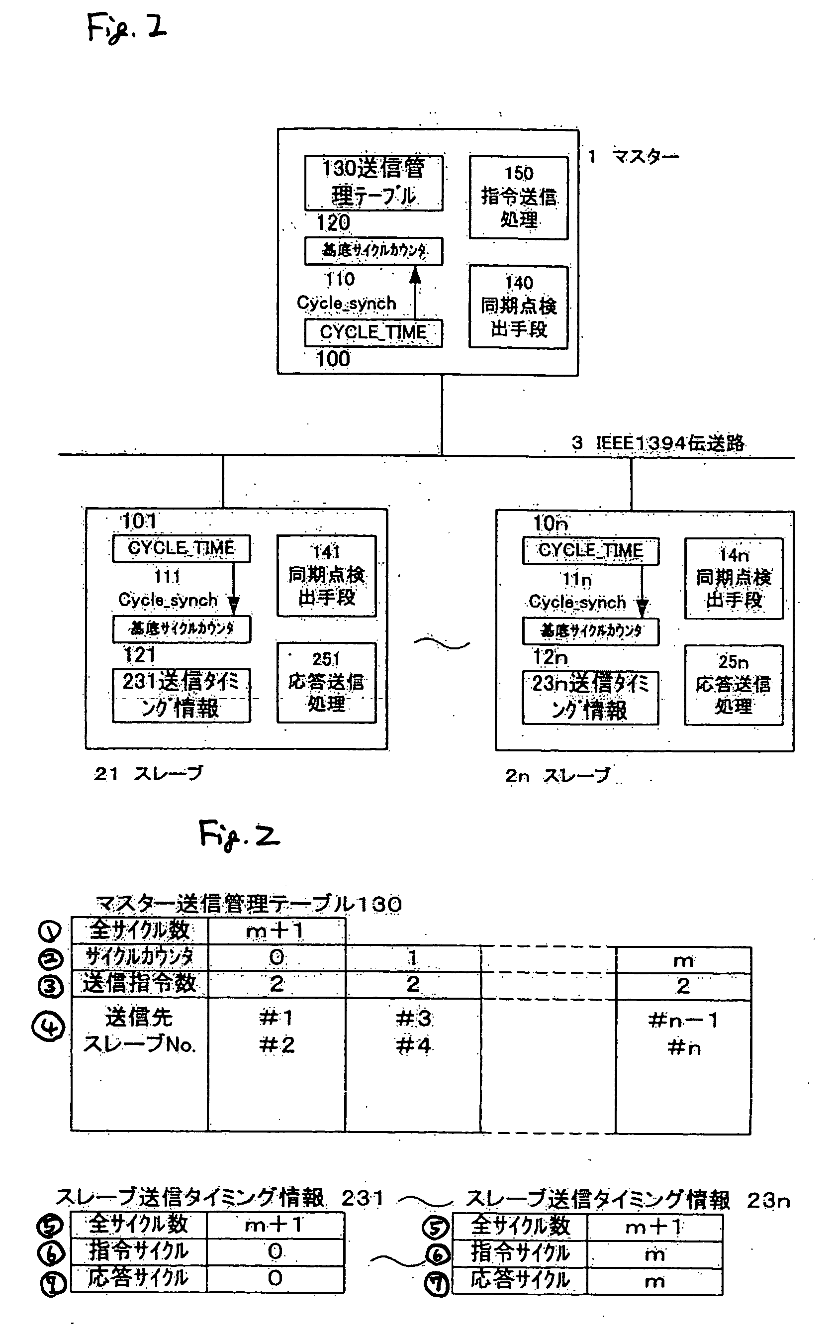
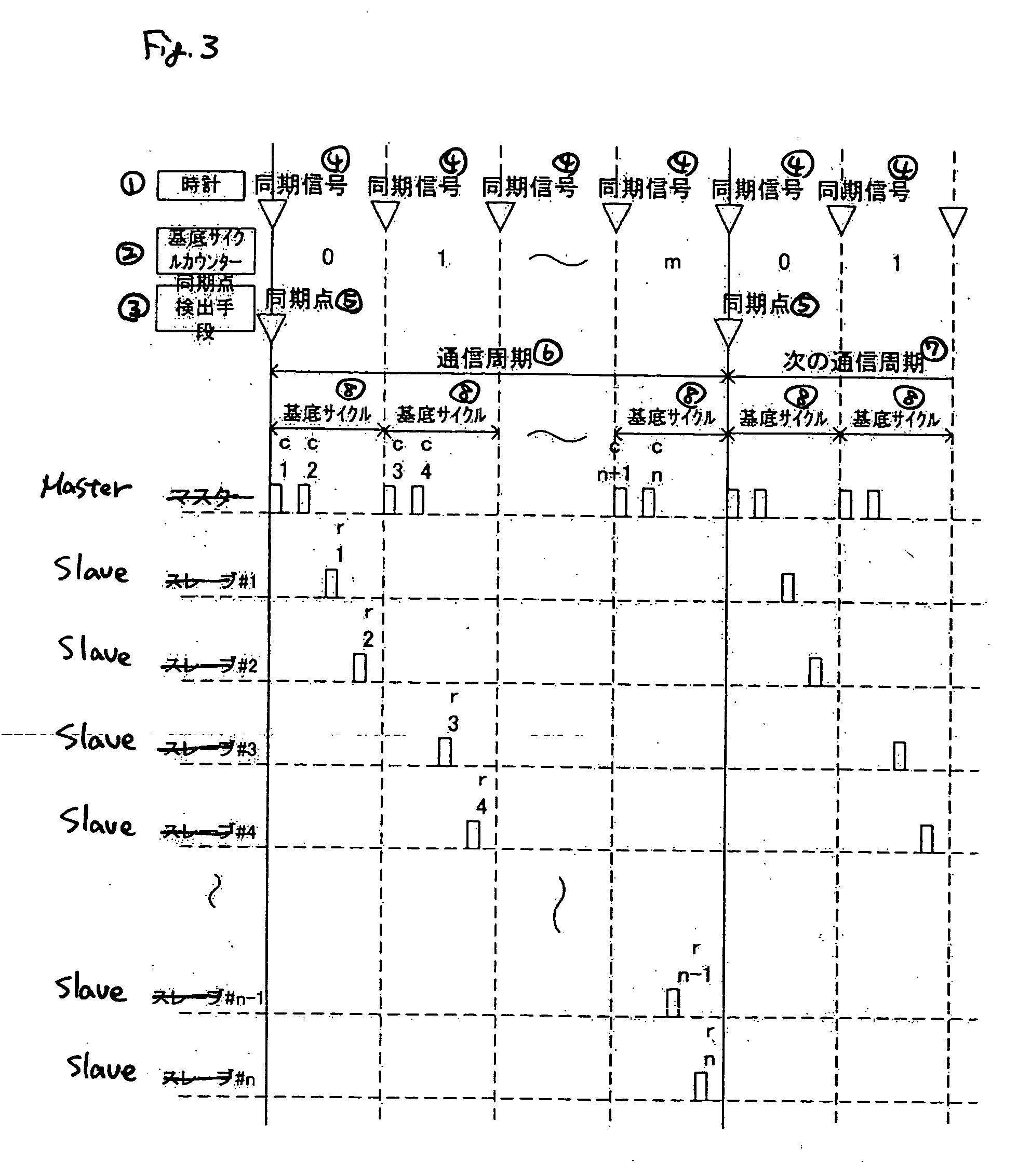
[0059]FIG. 1 shows a specific embodiment of the first invention where reference 1 represents a master, reference 2i (i=1, 2, . . . n) represents a slave, and reference 3 represents a transmission path of IEEE1394. Reference 10j (j=0, 1, . . . n) represents a CYCLE_TIME register serving as a clock part of the master and each slave. Fro...
second embodiment
[0069] Next, an embodiment of the synchronization point detecting section 14j that synchronizes the updates of the base cycle counter 12j will be described. As a matter of fact, detection of a synchronization point is made individually for the master 1 and each slave 2i and the result is reflected on the value of the base cycle counter 12j of each station. A cycle that serves as its synchronization point requires the same determination result by all stations. While the value of the base cycle counter 12j is 0 at this synchronization point and thereafter the value of the base cycle counter 12j is incremented every time a base cycle elapses, that is, the Cycle_synch event 11j takes place and the value of the base cycle counter 12j returns to 0 at the next synchronization point after a predetermined communication period has elapsed in this embodiment, transition of the value of the base cycle counter 12j is not limited thereto but the value may be decremented. A base cycle counter valu...
third embodiment
[0072] A third invention that is another method for the synchronization point detection processing 14j will be described. In a synchronization point detection processing 140 of the master 1, a synchronization point detecting section is activated by a Cycle_synch event 11j per natural period and only increments the base cycle counter 120 and determines whether the value is 0. The instruction data transmitted from the master to each slave in accordance with the transmission management table includes the CYCLE_TIME register value at the next synchronization point.
[0073] Processing at each slave 2i will be described in line with FIG. 9. First, the processing determines whether instruction data from the master 1 is received in the last base cycle at S4000. In case the data is received, the processing extracts at S4001 the CYCLE_TIME register value as the next synchronization point in the received instruction data. Next, at S4002, the processing obtains the difference between the cycle_c...
PUM
 Abstract
Description
Claims
Application Information
 - R&D
- Intellectual Property
- Life Sciences
- Materials
- Tech Scout
- Unparalleled Data Quality
- Higher Quality Content
- 60% Fewer Hallucinations
Browse by: Latest US Patents, China's latest patents, Technical Efficacy Thesaurus, Application Domain, Technology Topic, Popular Technical Reports.
© 2025 PatSnap. All rights reserved.Legal|Privacy policy|Modern Slavery Act Transparency Statement|Sitemap|About US| Contact US: help@patsnap.com


