Arrangement for dividing a filter output signal

a filter output and arrangement technology, applied in the direction of electrical equipment, transmission, coupling devices, etc., can solve the problems of amplifier cost saving, reduce the loss of low-noise amplifier units of receivers, and reduce the loss of dividers

Active Publication Date: 2006-11-09
INTEL CORP +1
View PDF9 Cites 0 Cited by
  • Summary
  • Abstract
  • Description
  • Claims
  • Application Information

AI Technical Summary

Benefits of technology

[0008] The invention has the advantage that the losses of the low-noise amplifier unit of the receiver are reduced. This is due to the fact that a transmission line is not needed between the antenna filter and the divider, and also due to the fact that the dielectric losses of the divider can be reduced as compared to the prior art. The reduction of losses means an improvement in the noise figure of the amplifier unit, in which case inferior noise qualities can be allowed for its both LNAs, which further means saving of costs in amplifiers. In addition, the invention has the advantage that it simplifies the structure of the amplifier unit, which means saving of costs in production.

Problems solved by technology

The reduction of losses means an improvement in the noise figure of the amplifier unit, in which case inferior noise qualities can be allowed for its both LNAs, which further means saving of costs in amplifiers.

Method used


Image

  • Arrangement for dividing a filter output signal
  • Arrangement for dividing a filter output signal
  • Arrangement for dividing a filter output signal

Examples


Embodiment Construction

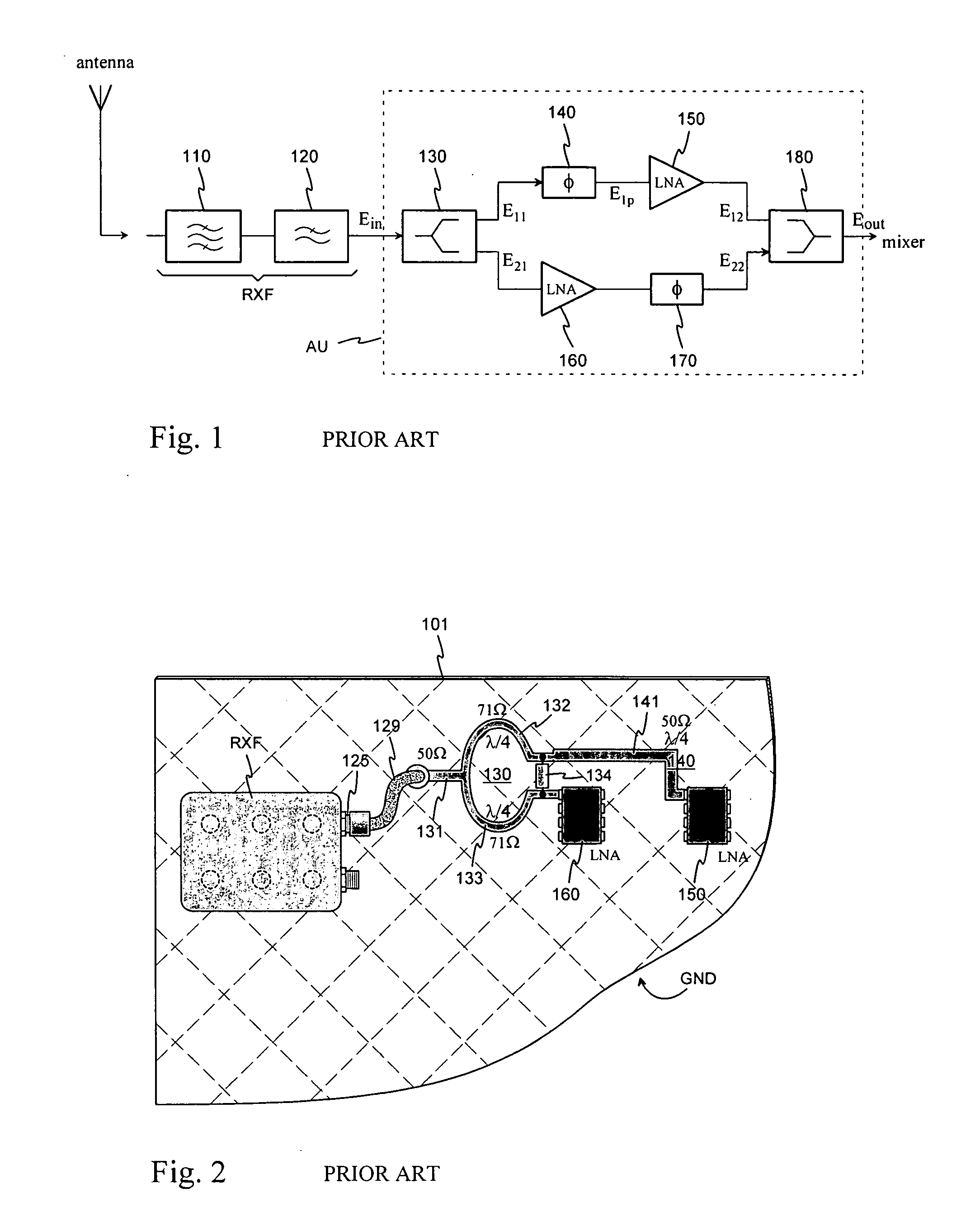
[0015]FIGS. 1 and 2 were already discussed in connection with the description of the prior art.

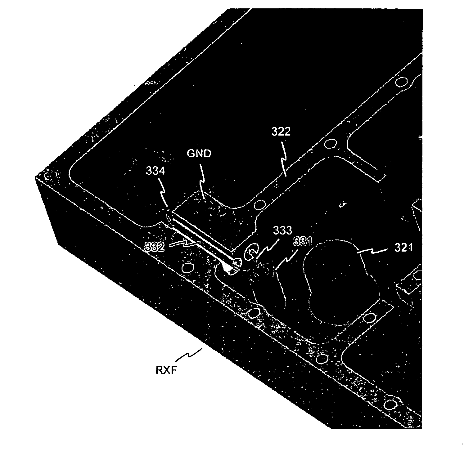
[0016]FIG. 3 shows an example of an arrangement according to the invention for dividing the received signal before amplification. The figure shows part of the receiver antenna filter with its cover removed. The antenna filter RXF is of the resonator type and consists of air-insulated coaxial resonators connected in series. The bottom of the whole filter, its side walls and cover form a conductive filter housing, the inner space of which is divided by conductive partition walls into resonator cavities. The partition walls delimiting a single cavity and parts of the side walls of the filter form the outer conductor of the resonator in question. In the cavity there is the inner conductor of the resonator, which inner conductor is galvanically fastened to the bottom at its lower end, and thus the resonator is shorted at its lower end. At the upper end each resonator is electrically open, and ...
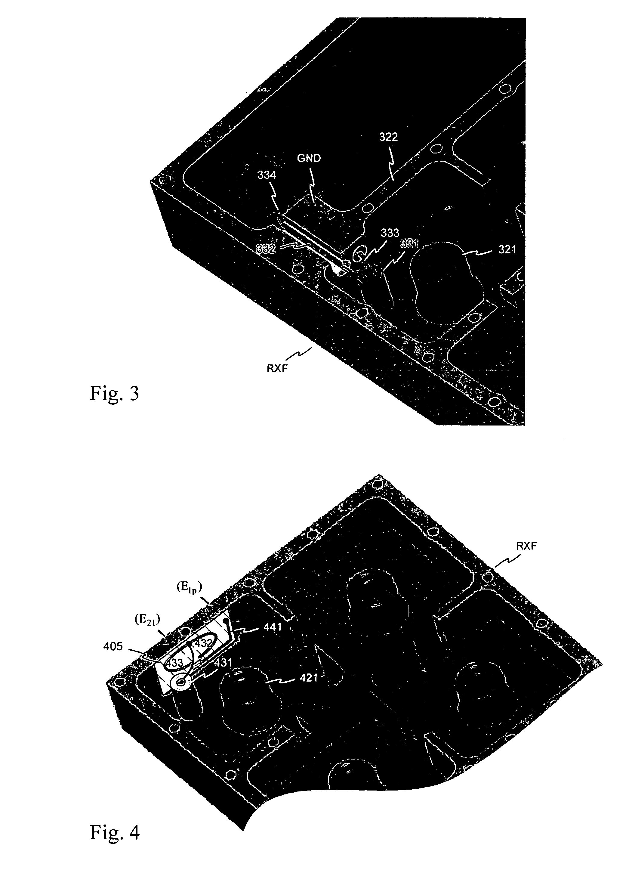

PUM


Abstract

An arrangement for dividing the output signal of the antenna filter of a radio receiver to two different paths, such as two parallel low-noise amplifier branches of a base station. The divider circuit is physically integrated into a resonator-type antenna filter (RXF). This takes place by placing some conductors (332, 333) of the divider inside some conductive part of the filter structure or the resonator cavity and by using the coupling conductor (331) of the output resonator as part of the input line of the divider at the same time. As the divider is used a Wilkinson divider. Due to the arrangement, a transmission line between the antenna filter and the divider becomes unnecessary, and the dielectric losses of the divider are reduced as compared to the prior art, in which case correspondingly inferior noise qualities can be allowed for low-noise amplifiers.

Description

[0001] The invention relates to an arrangement for dividing the output signal of the antenna filter of a radio receiver to two different paths. The arrangement is suitable for use on the receiving side of base stations of mobile communication networks and satellite receivers, for example, wherein the low-noise amplifier unit consists of two parallel and phased amplifier branches. BACKGROUND OF THE INVENTION [0002] In all radio receivers, the first amplifier after the antenna when entering the receiver should be especially low noise type, because the signal level at the input of this amplifier is very low, and the additional noise caused by the amplifier is amplified in all the following amplifier stages. An abbreviation LNA is used of such a low-noise preamplifier. Some allowed maximum value is generally specified in receivers for the total noise figure of the LNA and its input and output circuits. Losses on the transmission path cause signal attenuation, which directly increases th...

Claims


Application Information

Patent Timeline
Patent Type & Authority Applications(United States)
IPC IPC(8): H04B1/10H04B1/18H01PH01P1/202H01P1/205H01P5/00H01P5/12H04B1/06
CPCH01P5/12H01P1/2053
Inventor NIIRANEN, ERKKINARHI, HARRIPUOSKARI, JUKKAKOSKELA, PERTTI
Owner INTEL CORP
Why Eureka
Try Eureka