

Low noise amplifier for bioelectricity detection
A low-noise amplifier and bioelectric technology, applied in the direction of amplifier combination, improved amplifier to reduce noise influence, etc., can solve the problems of circuit electrode DC offset offset, inability to guarantee signal quality, poor noise performance, etc.
- Summary
- Abstract
- Description
- Claims
- Application Information
AI Technical Summary
Problems solved by technology
Method used
Image

Examples
Embodiment 1
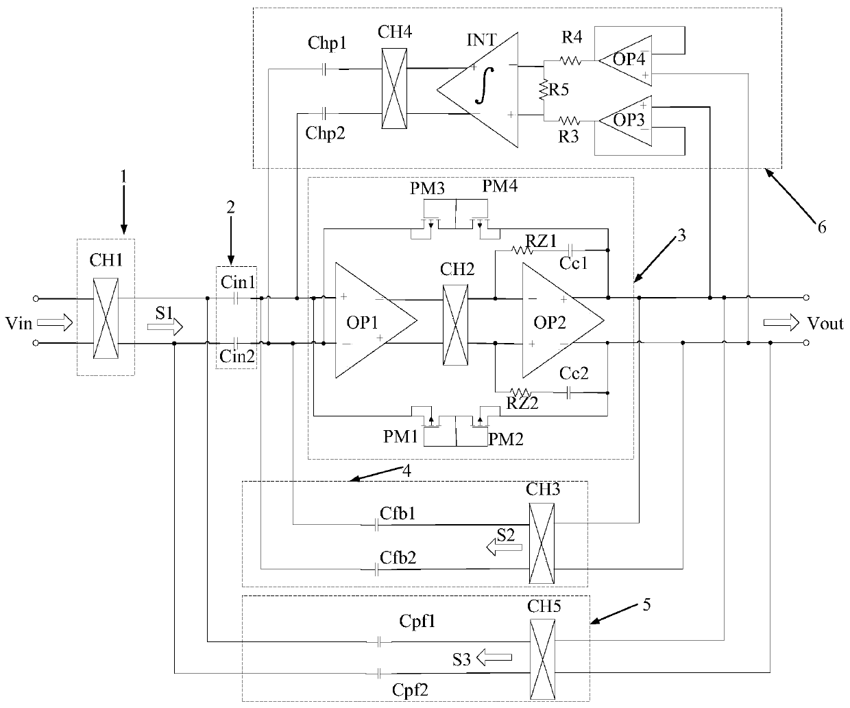
[0065] See figure 1 , figure 1 A circuit structure diagram of a low noise amplifier for bioelectricity detection provided by an embodiment of the present invention. The low-noise amplifier is suitable for the analog front-end circuit of bioelectric detection, including: input chopper circuit 1, input coupling capacitor module 2, two-stage operational amplifier module 3, capacitor negative feedback loop 4, positive feedback input impedance boosting loop 5 and an electrode DC offset elimination loop 6, wherein the two-stage operational amplifier module 3 is a low-noise two-stage operational amplifier module.
[0066] The input chopper circuit 1 includes a first chopper switch CH1, the first input terminal and the second input terminal of the first chopper switch CH1 are correspondingly electrically connected to the first electrode and the second electrode of the analog front-end circuit to receive the input low frequency signal Vin , and the first chopping switch CH1 modulates...
Embodiment 2
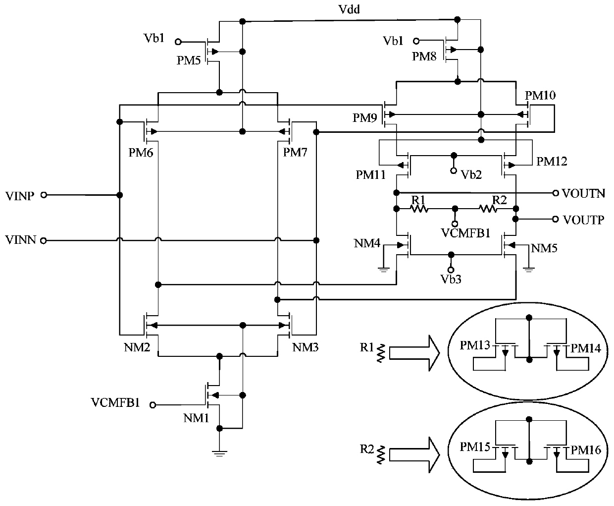
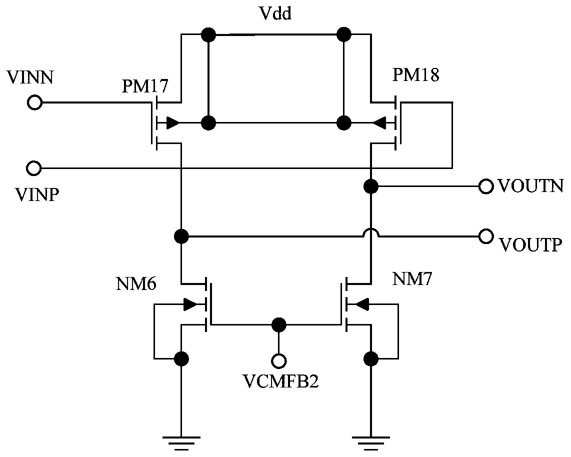
[0074] See figure 1 , figure 1 The two-stage operational amplifier module 3 includes: a first operational amplifier OP1, a second chopper switch CH2, a second operational amplifier OP2, a first PMOS transistor PM1, a second PMOS transistor PM2, a third PMOS transistor PM3, and a fourth PMOS transistor. The tube PM4, the first Miller compensation capacitor Cc1, the second Miller compensation capacitor Cc2, the first zeroing resistor RZ1 and the second zeroing resistor RZ2. in,
[0075] The non-inverting input terminal and the inverting input terminal of the first operational amplifier OP1 are correspondingly electrically connected to the non-inverting input terminal and the inverting input terminal of the two-stage operational amplifier module 3, and the inverting output terminal and the non-inverting output terminal of the first operational amplifier OP1 are correspondingly electrically connected On the first input end and the second input end of the second chopper switch CH...
Embodiment 3
[0086] See figure 1 , figure 1 The electrode DC offset elimination loop 6 includes: the third operational amplifier OP3, the fourth operational amplifier OP4, the third resistor R3, the fourth resistor R4, the fifth resistor R5, the integrator INT, the fourth chopper switch CH4, the A coupling capacitor Chp1 and a second coupling capacitor Chp2. in,
[0087] The inverting input of the third operational amplifier OP3 is electrically connected to its output to form a unity gain amplifier, and the non-inverting input of the third operational amplifier OP3 is electrically connected to the non-inverting output of the two-stage operational amplifier module 3; the inverting of the fourth operational amplifier OP4 The input end is electrically connected to its output end to form a unity gain amplifier, and the non-inverting input end of the fourth operational amplifier OP4 is electrically connected to the inverting output end of the two-stage operational amplifier module 3; one end ...
PUM
 Abstract
Description
Claims
Application Information